Battery Solution Testing for Robotics: HIL Duty-Cycle
What a “Robotics-Grade” battery solution Actually Has to Survive
Most cell datasheets are written for either handheld electronics or electric vehicles, so when a robotics integrator asks me to qualify a pack for an autonomous mobile robot (AMR), an automated guided vehicle (AGV), or a humanoid platform, the first thing I do is throw the EV cell spec away and start a fresh validation plan. A warehouse robot does not glide at a constant 30 km/h on a smooth highway. It crawls, accelerates, brakes, lifts, hovers at a dock, and idles in front of a charging cabinet for hours. The duty cycle is closer to a forklift than to a car, the shock profile is closer to a power tool than to a phone, and the regulatory target is industrial, not automotive. That is why every serious battery solution testing for robotics program we run at Horizon Power is anchored to three pillars: HIL duty-cycle validation against a real AMR mission profile, mechanical abuse (vibration + shock + drop), and thermal abuse to IEC 62619 with UN38.3 transport pre-qualification stacked on top.
In this guide I will walk through the test architecture we use, the pass/fail thresholds that actually mean something on a customer site, and the documentation that lets a fleet buyer accept the pack without re-running a six-month qualification themselves. If you are a systems integrator, a robotics OEM hardware lead, or a procurement engineer evaluating a custom battery solution, the workflow below is what you should be asking your supplier to demonstrate.
Step 1: Codify the Robot Mission Profile Before You Buy the First Cell
The single biggest mistake I see in robotics battery programs is ordering 280 Ah LiFePO4 prismatic cells because the energy number “looks good on paper,” then realising six months later that the C-rate cannot sustain the robot’s lift-and-go pattern. A lithium battery pack for robotics is rated against a duty cycle, not against capacity.
For each robot platform we ask the OEM to deliver a one-page mission profile covering:
- Drive current envelope: peak (1–3 s), continuous cruise (30–60 s), idle draw on the auxiliary bus.
- Lift / manipulator transient: peak torque current drawn by the lift motor, expected pulse width, and duty factor.
- Regen / braking: peak regenerative current and energy returned per stop event.
- Thermal environment: ambient min/max, floor temperature after a fast-charge, and proximity to hydraulic or motor heat sources.
- Charge cadence: opportunity charging at 1C for 10 minutes vs full-cycle to 100% SoC, and the target SoC window the fleet manager will actually operate in.
That profile becomes the basis for the HIL bench script in Step 2 and the thermal chamber profile in Step 4. If the supplier cannot tell you the pack has been tested against your specific mission, it has not been tested for your robot — it has only been tested for a generic datasheet.
Step 2: HIL Duty-Cycle Bench — Where the Pack Meets Reality
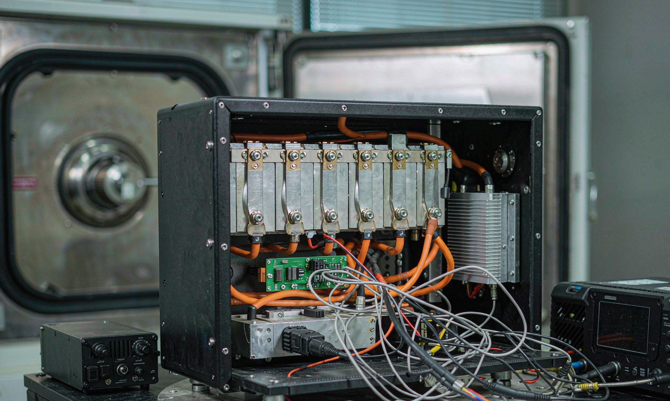
A hardware-in-the-loop (HIL) bench is a programmable DC load + DC source + thermal chamber that replays a digital twin of the robot's mission. We use a 4-quadrant supply so that the test rig can both source (charging) and sink (regen braking) energy in real time, and a programmable electronic load to draw the lift-transient pulse shape. The pack sits on a thermal plate set to the worst-case ambient the integrator specified, and we route coolant through the cold plate at the same flow rate the robot will deliver in production.
The script I run for a typical 24 V / 60 Ah warehouse AMR looks like this, looped for 1,000 equivalent cycles:
- Discharge at 0.3C cruise for 90 s (corridor travel).
- Pulse discharge at 1.5C for 3 s (ramp up to a dock).
- Hold at 0.05C for 20 s (docking alignment).
- Pulse regen at –0.8C for 2 s (braking into a charge dock).
- Standby at 0.01C for 60 s (idle waiting for WMS task).
Each cycle we log pack voltage, cell-level voltage (every cell, every cycle), BMS temperatures, and DC bus current. Acceptance criteria for a custom battery solution in this loop are:
- Capacity fade ≤ 3% over 1,000 cycles at the documented SoC window.
- Cell-to-cell voltage delta at end of pulse ≤ 30 mV (proves balancing is healthy, not just “OK”).
- BMS MOSFET temperature rise ≤ 35 K above ambient at 1.5C peak.
- No CAN / SMBus error frames over the 1,000-cycle run (proves comms robustness under EMI).
If a supplier cannot show you the cell-level delta vs cycle number, they have not run this test. They have run a box-level cycle and inferred.
Step 3: Vibration, Shock and Drop — Mechanical Validation the Robot Will Not Tell You About
Robots vibrate. AMRs roll over expansion joints, threshold strips, and cable covers hundreds of times per shift. Humanoids get dropped during commissioning. A pack that survives HIL but cracks a busbar weld at 7 Hz because no one PSD-profiled the floor will fail in week 3 at the customer site. We run mechanical abuse per IEC 60068-2-6 (vibration) and IEC 60068-2-27 (shock), but with amplitudes tuned to the robot’s real mounting rather than the standard’s defaults:
- Random vibration: 5–500 Hz, 0.05 g²/Hz PSD, 3 h per axis, with the pack mounted on the robot's actual isolators (not on a steel fixture).
- Mechanical shock: 30 g, 11 ms half-sine, 3 shocks per axis, both positive and negative directions.
- Drop test: 1.2 m onto concrete, 6 faces, 1 corner, 3 edges — only required for packs destined to mobile service robots or humanoids.
- Post-shock functional check: 0.5C discharge pulse after each shock event; any voltage deviation > 5% from pre-shock baseline flags a busbar or sense-lead fault.
The busbar weld is the most common silent failure. We inspect a sample of cells after the run by cross-sectioning the weld interface; a pull-test to ≥ 1.5 kN is the threshold we accept for a production run. Anything below that gets a re-spec to laser-welded nickel-plated copper with a redundant sense wire.
Step 4: Thermal Abuse and Safety — IEC 62619 Stacked with UN38.3
For an industrial lithium battery pack, IEC 62619 is the baseline standard; UN38.3 is the transport prerequisite; UL 1973 is sometimes added if the robot will be installed in a North American facility. We test the pack as a unit (not cell-by-cell) because the BMS and enclosure contribute as much to safety outcome as the cell chemistry does.
The thermal abuse tests we run and document for every pack design:
- External short circuit: ≤ 5 mΩ, 1 h or until protection triggers, monitored for casing temperature rise.
- Impact: 9.1 kg drop from 610 mm onto the largest face.
- Drop: 1 m onto concrete, 6 orientations.
- Thermal abuse: ramp to 85 °C at 5 °C/min, hold 3 h. No fire, no explosion, no venting beyond the designed vent.
- Overcharge: charge at 1C to 200% SoC with BMS bypassed. Cell must not rupture or ignite.
- Forced discharge: reverse-charge at 1C into a depleted cell. No fire.
For UN38.3 we stack T.1 altitude simulation (11.6 kPa, 6 h), T.2 thermal cycling (–40 °C to +75 °C, 10 cycles), T.3 vibration, T.4 shock, T.5 external short, T.6 impact, T.7 overcharge, and T.8 forced discharge. A pack that passes IEC 62619 plus UN38.3 can be shipped by air, sea, or road under any of the standard dangerous-goods declarations.
Step 5: EMC, ESD and Conducted Emissions — the Quiet Killer of Robot Uptime
Robots live in electrically noisy environments — variable-frequency drives, servo inverters, induction chargers, and welding cells all share the same bus. A pack whose BMS glitches every time the robot docks will look like a software bug to the fleet manager but is actually a conducted-emissions failure. We test the pack to EN 61000-6-2 (immunity for industrial environments) and EN 61000-6-4 (emissions), with three additions tuned to robotics:
- ESD: ±8 kV contact / ±15 kV air, applied to the enclosure, BMS port, and any user-accessible connector.
- EFT/burst: ±2 kV on DC power lines, ±1 kV on signal lines.
- Surge: ±1 kV line-to-line, ±2 kV line-to-ground on the DC bus.
The acceptance criterion is zero BMS lock-up, zero CAN error frames, and no spurious contactor drop-out across the full test suite. We have seen packs from otherwise reputable cell brands fail this step because the BMS PCB layout did not include a common-mode choke on the sense lines — and they would have caused hundreds of hours of unplanned downtime per robot per year if shipped.
Step 6: Documentation That Lets a Fleet Buyer Accept the Pack
Validation data is useless if it is not organised the way a buyer's quality team can read it. For every custom battery solution we deliver to a robotics OEM, we hand over a pack DVT (Design Validation Test) report with this structure:
- Executive summary, pack specs, BMS firmware version.
- Mission profile used for HIL (with the OEM's signature).
- HIL bench plots: capacity fade curve, cell delta histogram, thermal profile.
- Mechanical test data: PSD profile used, before/after functional check, weld pull-test results.
- IEC 62619 + UN38.3 third-party certificates, with cell-level traceability.
- EMC / ESD test report from an accredited lab (we use TÜV Rheinland or TÜV SÜD).
- FMEA with RPN scoring, mitigation status, and any residual risk sign-off from the OEM's safety lead.
If a supplier hands you a “datasheet” instead of a DVT pack, ask them to run Step 2 against your mission profile before you commit. The cost of one good HIL run is trivial next to the cost of a field recall on 200 robots.
FAQ — Battery Solution Testing for Robotics
How long does a full robotics pack validation take from clean sheet?
For a 24–48 V pack in the 30–100 Ah range using a qualified cell, the bench tests (HIL + mechanical + thermal) take about 8–10 weeks once the mission profile is locked. Add 4–6 weeks if you also need UN38.3 transport certification at a third-party lab, and another 2–3 weeks for EMC if you do not already have a family test report you can leverage.
Can I reuse EV or e-mobility cell data for my AMR?
No. EV duty cycles are smooth and long; AMR duty cycles are burst-heavy and regen-heavy. The cell-to-pack thermal stress and the BMS balancing workload are completely different. EV cell data will mislead you on both capacity fade rate and on peak pulse headroom.
What SoC window should I run my fleet at to extend cycle life?
For LiFePO4 in robotics service, we recommend 20–80% SoC for opportunity-charged fleets (warehouse AMRs, AGVs) and 10–90% for humanoid or service robots that get a full overnight charge. Keeping the average SoC around 45–55% roughly doubles cycle life compared with a 0–100% cycling regime, based on our field data over the last three years.
Do I need IEC 62619 even if my robot stays indoors?
Yes. IEC 62619 is the industrial lithium battery standard regardless of indoor or outdoor use, and most large fleet buyers in Europe and North America require it as a contractual deliverable. Outdoor or cold-storage robots may also need IEC 60068 cold-soak profiles on top of the IEC 62619 base.
How is robotics testing different from drone battery testing?
A drone battery prioritises energy density, peak C-rate, and lightweight pack assembly. A robotics pack prioritises cycle life, mechanical robustness, and field-serviceability. The cell format (cylindrical 21700/18650 for drones, prismatic for robots) and the BMS topology are usually different as well. We run two separate validation streams inside Horizon Power for exactly this reason.
What is the smallest pack size where a custom solution makes sense vs an off-the-shelf module?
In our experience, below roughly 1 kWh of energy and below 50 V nominal, an off-the-shelf module is almost always the right choice. Above that, the integrator-specific mission profile, enclosure, BMS, and connector stack-up start to dominate the bill of materials, and a custom battery solution starts to pay back through lower integration cost and fewer field failures.
How do you handle field returns and root-cause analysis?
Every Horizon Power pack ships with a manufacturing date code and cell-level traceability. When a customer returns a pack, we tear it down in our failure-analysis lab, cross-reference the cell barcodes against the HIL and IEC 62619 reports, and issue a written RCA within 10 working days. That loop is what closes the test-to-production feedback chain and keeps the next revision of the pack safer than the last.