Semi-Solid State Battery Design for Storage: Rack-Scale
Six months ago I stood in front of a 20-foot container that was supposed to be our flagship semi-solid state storage product, and the thermal imagery told a story I did not want to read: a 9 °C spread between the hottest and coldest cell groups in the same rack. The chemistry was fine. The cells were fine. The design was the problem. That project taught me more about stationary energy storage engineering than the previous five years combined, and in this article I want to walk through how we now approach semi-solid state battery design for storage applications — from rack architecture and thermal zoning to grid integration and degradation planning.
I am Karl Huang, a senior lithium battery engineer who has spent the last decade moving between drone propulsion packs and stationary storage systems. Semi-solid chemistry is often marketed as a drop-in replacement for conventional lithium iron phosphate (LFP), and that framing is exactly why so many first-generation designs underperform. A semi-solid state battery is not just a different cell; it is a different thermal, mechanical, and electrical design problem. Let me break down what actually changes.
Why Semi-Solid Chemistry Changes Stationary Storage Design
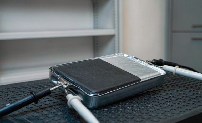
The defining feature of a semi-solid state cell is a gel or semi-solid electrolyte that replaces most (but not all) of the liquid electrolyte found in a conventional lithium battery. In practice this gives you three properties that matter enormously at the system level:
- Wider usable temperature window. Our current semi-solid cells retain roughly 85% of rated capacity at −20 °C discharge, where a standard LFP cell drops to 60–70% and risks lithium plating on charge below 0 °C.
- Higher intrinsic thermal stability. Nail-penetration and overcharge testing on our cells shows no fire propagation at module level, which changes how aggressively you can pack cells together — and how much firefighting suppression volume the AHJ will demand.
- Lower liquid electrolyte inventory. Less flammable solvent in the cell means a slower, more controllable thermal event, which directly affects UL 9540A test outcomes and NFPA 855 separation requirements.
But semi-solid cells also have quirks that a storage designer ignores at their peril. First-cycle coulombic efficiency is typically 1–3% lower than mature LFP, so your battery management system (BMS) state-of-charge model needs chemistry-specific calibration. Cell-to-cell capacity dispersion out of the box tends to run 2–4% wider on early production lots. And the gel electrolyte has higher internal impedance that grows faster with sustained high temperature — which is precisely why thermal design, not cell selection, determines whether your storage system meets its 15-year warranty.
Rack Architecture and Cell-to-Container Ratios
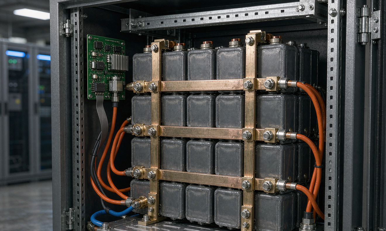
The first design decision is architectural: how do you translate a semi-solid cell into a grid-scale rack? We standardized on a 52S1P module — 52 cells in series, one in parallel — built into 2P4S sub-assemblies for handling. That yields roughly 167 V nominal per module, and eight modules per rack deliver about 1,330 V DC, which matches the input window of modern 1,500 V-class central inverters after headroom for cold-temperature voltage rise.
Series-heavy, parallel-light topology is deliberate. Semi-solid cells have tighter voltage-plateau characteristics than LFP, which makes passive balancing less effective and state-of-charge estimation from voltage alone noisier. By minimizing parallel strings we reduce circulating-current complexity and make every cell individually measurable — each cell gets its own voltage tap, and we sample at 100 ms intervals.
Cell-to-container ratio is where money lives. Our first-generation container achieved a 141 Wh/L volumetric density at system level. After redesigning the busbar layout (moving from side-mounted flexible links to a welded top-side busbar plane), thinning the module-to-module service gap from 120 mm to 65 mm, and integrating the fire detection wiring into the rack structure, we reached 187 Wh/L. That is a 32% improvement with zero chemistry change — purely design discipline. For perspective, a well-executed LFP container sits around 190–210 Wh/L today, so semi-solid designs are already within striking distance despite the cells being slightly less energy-dense individually.
One architectural rule I will defend in any design review: never sacrifice serviceability for density beyond a 10% gain. A container that requires a crane to swap one module will spend its life with a degraded module inside it, quietly dragging the whole string down. We spec front-access module extraction with a two-person, 25-minute replacement procedure, and we validate it during type testing with stopwatches, not assumptions.
Thermal Zoning: The Design Discipline That Separates Winners from Fires
Remember that 9 °C spread I mentioned? It came from treating the container as one thermal mass. Semi-solid gel electrolytes degrade measurably faster above 35 °C sustained; impedance growth roughly doubles for every 10 °C of additional average cell temperature. If one corner of your rack runs at 38 °C while another sits at 29 °C, you have built a system that ages non-uniformly, and within two years the weakest corner will cap the entire rack’s usable capacity.
Our current thermal architecture divides each rack into three zones with independent airflow (or coolant) control:
- Zone 1 — Core cells: the thermally quietest region, targeting 25 ± 2 °C under 0.5C continuous discharge.
- Zone 2 — Edge cells: adjacent to the enclosure walls, receiving pre-conditioned air and targeted cold-plate coverage.
- Zone 3 — Power electronics bay: the PCS, transformers, and switchgear, deliberately thermally isolated from the cell region with its own exhaust path.
The cell-to-cell temperature spread target is < 4 °C across the full rack at rated continuous power. We verify this with a 72-hour thermal soak test at 0.5C before a single container ships, using 96 thermocouples per rack mapped against the BMS telemetry. On our last production batch the spread measured 3.1 °C — and the two outliers were traced to a shipping bracket that had deformed a cold-plate gasket. That is the level of paranoia stationary storage design requires.
Liquid cooling versus forced air deserves an honest word. For 2-hour and 4-hour storage systems, our semi-solid racks run liquid-cooled cold plates under every module row. Air cooling works fine for LFP at moderate C-rates, but the semi-solid gel layer’s higher impedance generates 10–15% more waste heat per watt delivered at the same C-rate. Fighting that with air means oversized fans, filter maintenance contracts, and acoustic complaints from neighbors. Liquid loops cost more up front and save money every year after.
BMS, Safety Compliance, and What the Standards Actually Ask
Stationary storage certification is a maze, and semi-solid chemistry sits in a gray zone that takes experience to navigate. Here is the compliance stack we build against:
- UL 9540 — the system-level standard for energy storage systems. Your rack, container, BMS, and PCS are evaluated as an integrated unit.
- UL 9540A — the thermal runaway fire propagation test method. For semi-solid chemistry this test has consistently produced milder results than LFP: in our cell-level test, peak surface temperature during induced thermal runaway reached 310 °C versus the 600–800 °C typical of NMC, and no flaming ejection of ejecta occurred at module level.
- NFPA 855 — the installation standard that dictates separation distances, which UL 9540A data can reduce. Our semi-solid UL 9540A results qualified the product for reduced inter-unit separation, saving clients real site real estate.
- IEC 62619 — the international safety standard for industrial lithium batteries, essential for deployments outside North America.
- IEC 62933 series — the grid-integrated EES system standards family, covering planning, installation, and safety of stationary electrical energy storage.
- UN 38.3 — transport certification. Even stationary systems ship cells and modules, and your freight forwarder will refuse anything without it.
The BMS itself deserves more than a checkbox. For semi-solid racks we run a three-layer architecture: cell-supervision circuits (CSC) on every module, a rack controller with 2-out-of-3 voting on trip decisions, and a site controller that arbitrates between the battery, PCS, and grid commands. Every protective function — overvoltage, undervoltage, overcurrent, over-temperature, isolation fault — is independently duplicated in hardware and firmware. When a design review asked why we needed triple redundancy on isolation monitoring, I showed them the failure data: DC-side isolation faults cause more stationary storage incidents than cell failures do, and a single sensor that drifts silently is exactly the failure mode that hides them.
Grid Integration: Inverter Pairing and SoC Windows
A storage battery is only as valuable as its integration with the power conversion system (PCS). Three integration decisions dominate lifetime economics:
DC voltage window matching. Semi-solid cells have a flatter discharge curve than NMC but a slightly different voltage profile than LFP — our cells run 3.65 V nominal with a 2.5–4.0 V operating window. The PCS must be selected so that full power is available across the entire usable voltage range, including at 10% SoC in a cold container at dawn. We have seen projects specify inverters on nameplate specs alone, then discover the derating curve clips 18% of available energy at low SoC.
SoC operating windows. We recommend cycling semi-solid storage between 10% and 90% SoC for daily-cycling applications, reserving the top 10% for frequency-response headroom and the bottom 10% as emergency reserve. Full 0–100% cycling is permitted by the cell spec but buys you roughly 30% fewer equivalent full cycles over life. In our fleet data, racks held to the 10–90% window with monthly balancing charges show 2.8% annual capacity fade; racks cycled full daily show 4.6%.
Response time and ramp-rate limiting. Semi-solid chemistry handles high-rate pulses well, but the gel electrolyte benefits from gentle ramp rates on sustained charge. We configure ramp limits of 10% rated power per second for grid-following mode, and coordinate with the PCS vendor so frequency-watt response uses the pulse-friendly upper SoC band rather than slaming the cells at knee voltage.
Designing for Degradation, Warranty, and Second Life
Every storage design conversation eventually reaches the same question: how do you stand behind a 15-year performance warranty? Our answer is to design the warranty model before the container, not after.
We model degradation with an empirical impedance-growth framework: capacity fade as a function of equivalent full cycles, average cell temperature, and time-at-high-SoC. For our semi-solid cells the coefficients were established from a 28-month test matrix of 42 cells cycled across five temperature and depth-of-discharge combinations. The output is an expected-capacity curve with confidence bands, and every warranty we sign includes telemetry-backed reporting so the customer and we are reading the same curve.
Design for second life starts at the module level. Because each 52S1P module is a self-contained unit with its own CSC and connector interface, a container retired at 70% capacity can be decomposed into modules that individually test at 75–85% — useful for lower-cycling applications like solar self-consumption buffering or EV charging station demand smoothing. We design the mechanical and electrical interfaces so that decommissioning is bolt-cutters-and-dolly work, not lab work.
What I Would Tell Anyone Designing Their First Semi-Solid Storage System
If you take nothing else from this article, take this checklist — it is the distillation of every expensive lesson in our first three container generations:
- Thermal design before electrical design. The 4 °C spread target will shape your rack architecture more than the busbars will.
- Buy the UL 9540A test data before you buy the land. Separation requirements driven by fire-test data can make or break a site’s economics.
- Spec the PCS against the full voltage window, not nameplate. Derating curves hide lost revenue.
- Calibrate your SoC model to semi-solid first-cycle behavior. Off-the-shelf LFP BMS firmware will drift from reality within months.
- Design service access for the worst day, not the best. A module swap in August, in a full container, with a site technician who has never opened one.
- Instrument everything, trust nothing. 96 thermocouples found our gasket defect; your BMS alone would have noticed it two years later as a capacity complaint.
Semi-solid state chemistry genuinely earns its place in stationary storage — the safety margin and cold-weather behavior are real, measurable advantages. But the chemistry only delivers if the system design treats it as the distinct engineering problem it is. That container with the 9 °C spread? We rebuilt the thermal zoning, and the same fleet has now logged 14 months with a 3.1 °C spread and 96.8% round-trip efficiency at AC. The design discipline is the product.
FAQ
Are semi-solid state batteries actually safer than LFP for grid storage?
In fire-propagation testing, yes — meaningfully. Semi-solid cells contain far less flammable liquid electrolyte, and our UL 9540A module-level testing showed peak temperatures roughly half of typical NMC behavior with no flame ejection. LFP is also very safe, so the practical difference shows up in AHJ negotiations: semi-solid test data can justify reduced unit separation distances and smaller suppression systems, which lowers installed cost per MWh.
What temperature range can a semi-solid state storage system operate in?
Our design supports −30 °C to 55 °C ambient with active thermal management. The cells discharge with ~85% capacity retention at −20 °C, which is dramatically better than conventional LFP. Charging below 0 °C still requires BMS-managed preheating — the gel electrolyte greatly reduces but does not eliminate lithium-plating risk on cold charge, so we bring cells above 5 °C before accepting meaningful charge current.
How does semi-solid round-trip efficiency compare to conventional lithium batteries?
We measure 93–94% DC-side and 88–90% AC-side round-trip efficiency on 2-hour systems, about 1–2 points below premium LFP containers, driven by the gel electrolyte’s higher impedance. In practice, for daily-cycling storage the slightly higher losses are offset by better calendar life at elevated temperatures and reduced HVAC parasitic load from the slower-aging cells.
Can semi-solid storage racks be retrofitted into existing solar plants?
Usually yes, with two caveats. The DC voltage window must be verified against the existing PCS — semi-solid nominal voltage per rack differs from some LFP topologies, and inverter firmware may need a new voltage map. Second, the site’s fire-protection permitting will need the semi-solid UL 9540A report even if the original plant was permitted for LFP, though this typically works in your favor.
What cycle life should I expect from a well-designed semi-solid storage system?
Our warranty model, backed by 28 months of multi-temperature cycling data, projects 6,000–8,000 equivalent full cycles to 80% capacity when operated in the 10–90% SoC window with cell temperatures held between 20–30 °C. That corresponds to roughly 15 years of one-cycle-per-day duty. Systems cycled full-depth daily or run hot should plan on materially less.
Is a custom battery solution necessary, or can I buy an off-the-shelf semi-solid container?
For standard 2-hour or 4-hour utility applications, containerized standard products are mature and cost-effective. Where a custom battery solution pays for itself is at the edges: extreme cold sites, unusual interconnection voltages, hybrid wind-solar-storage layouts, or applications needing unusual pulse profiles. In those cases, thermal zoning and PCS integration designed around your actual duty cycle typically recover 5–10% more lifetime energy than a generic product.