Semi Solid State Battery Electrolyte Formulation: Polymer Hosts, Lithium Salts and Rheology Control Guide
I have spent the better part of a decade standing next to coating heads, dry rooms and formation
cabinets, and if there is one lesson that separates a working semi-solid state battery from an
expensive laboratory curiosity, it is this: the cell is won or lost in the electrolyte formulation
long before you ever close the pouch. Everyone talks about the cathode. Very few people talk about
the rheology window of the gel that has to wet a 20 mg/cm² electrode, survive calendering, and
still move lithium ions at 2 C on a cold morning.
This guide is my practical field notes on semi-solid state battery electrolyte formulation —
the polymer host, the lithium salt, the ceramic filler, the plasticiser, and the viscosity numbers I
actually specify on a production work order. It is written for engineers, cell buyers and integrators
who need to evaluate a solid state battery supplier or a custom lithium battery pack that uses a
semi-solid architecture, not for people looking for a press-release number.
What “semi-solid” actually means on the production floor
A semi-solid state battery sits between two extremes. On one side is the conventional liquid
lithium-ion cell, where a free-flowing carbonate electrolyte (roughly 1.0–1.2 M LiPF6
in EC/EMC/DMC) floods every pore and carries 100% of the ionic transport. On the other side is the
true all-solid-state cell, where a dense ceramic or sulfide layer does all the work and needs
10–50 MPa of stack pressure to stay in contact with the electrodes.
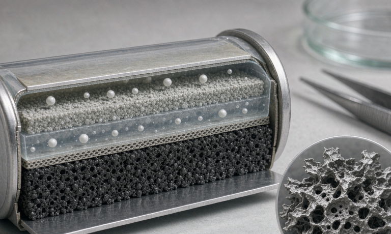
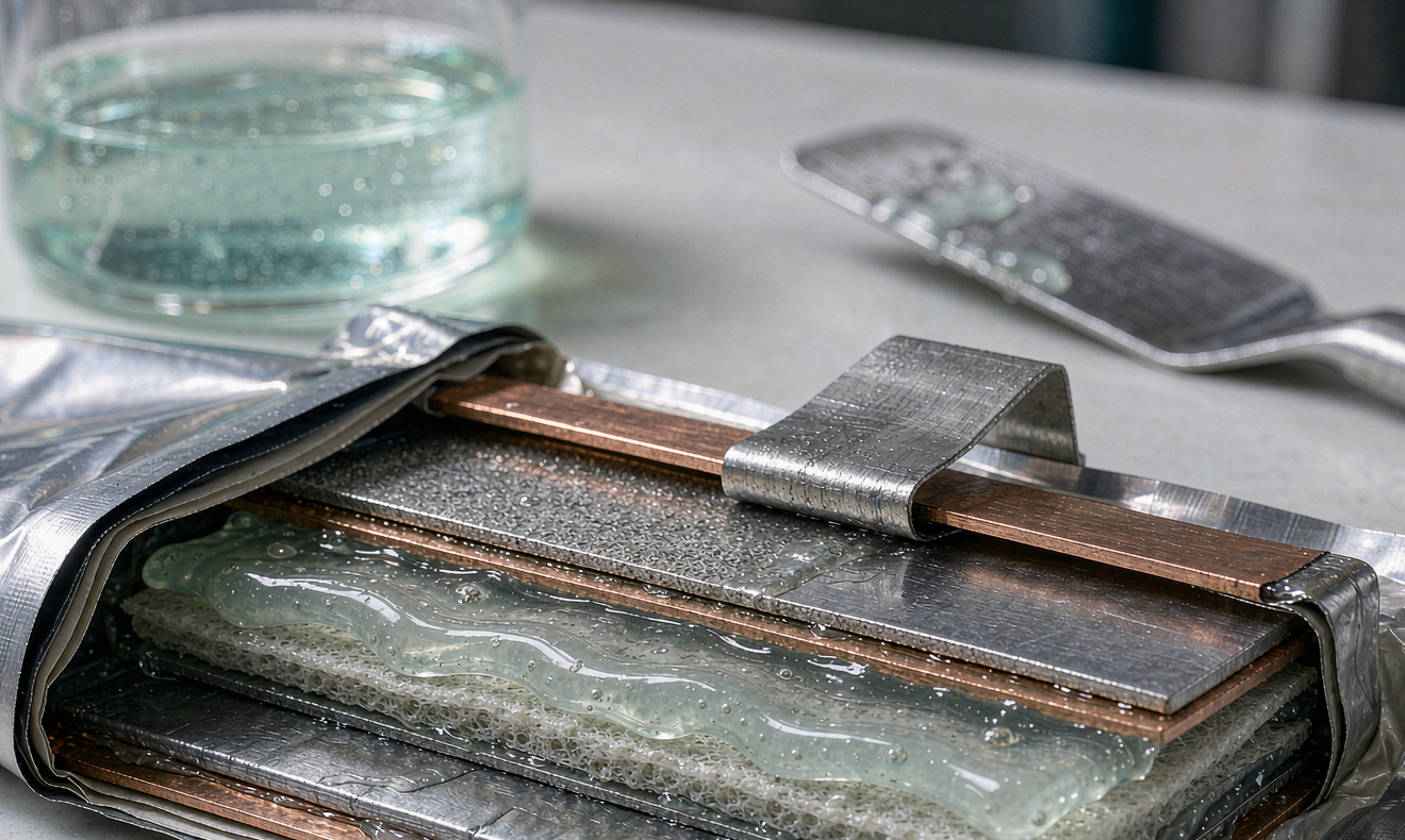
The semi-solid cell takes a middle road: a gel or paste electrolyte with a polymer scaffold holding
10–30 wt% of a liquid plasticiser or ionic liquid phase. Free liquid content drops by
50–80% compared with a conventional cell. You keep most of the interfacial contact and ionic
conductivity of a liquid system — typically 0.5–3 mS/cm at 25 °C — while picking up
the safety margin: no free electrolyte to leak, far lower vapour pressure, and a thermal abuse
behaviour that gives the BMS and the enclosure a fighting chance.
In our own pilot line data, moving a 5 Ah NMC811 pouch from a standard liquid formulation to a
semi-solid gel formulation raised the self-heating onset temperature from roughly 120 °C to
165–180 °C on accelerating-rate calorimetry, and cut the peak thermal runaway heating rate
by about 60%. That is the reason aerospace and high-end drone battery programmes keep asking for it.
The three-part backbone: host, salt, filler
Every semi-solid electrolyte I have qualified breaks down into three functional components. Get
these three right and the rest is process engineering.
1. The polymer host
The host provides mechanical integrity and, in the best designs, actually participates in ion
transport. The practical choices:
- PVDF-HFP — the workhorse. Dielectric constant around 8–11, excellent
electrochemical stability up to about 4.8 V vs Li/Li+, and it absorbs 30–60 wt% of
carbonate plasticiser without dissolving. Melting range 140–160 °C for the co-polymer, which
gives you a usable hot-press lamination step. - PEO (polyethylene oxide) — classic for true solid polymer electrolytes.
Ethylene-oxide-to-lithium ratios of 8:1 to 20:1 are typical, but PEO crystallises below about
60 °C and conductivity collapses to 10-7–10-6 S/cm at room temperature.
I only use it when the pack will be held above 45 °C continuously. - PAN and PMMA — good mechanical modulus and a wide window; PMMA in particular
gives excellent adhesion to the separator and works well in in-situ polymerised systems. - Polycarbonate-based hosts (PEC, PPC) — higher transference number than PEO
because the carbonate group coordinates Li+ more weakly and lets it hop; still expensive
and less mature at tonne scale.
2. The lithium salt
Salt choice is where most amateur formulations fail, because they optimise conductivity and forget
about the aluminium current collector.
- LiTFSI — thermally stable to above 350 °C, tolerant of residual moisture,
and highly conductive. But it corrodes the aluminium cathode foil above roughly 3.7–4.0 V vs
Li/Li+ unless you add a passivating additive. This is the single most common cause of a
cell that looks perfect for 50 cycles and then dies. - LiFSI — higher conductivity than LiTFSI and better film-forming on both
electrodes; also attacks Al at high voltage, and it is hygroscopic enough that dry-room discipline
matters. - LiPF6 — still the only salt that reliably passivates aluminium by
forming AlF3. Hydrolyses to HF above about 20 ppm of water, so it demands a −45 °C
dew point or better. - LiDFOB / LiBOB — excellent as 0.5–2 wt% co-salts or additives. They
build a robust cathode electrolyte interphase on high-nickel cathodes and scavenge HF.
3. The ceramic or inorganic filler
Fillers do three jobs: they raise ionic conductivity, they mechanically suppress lithium dendrites,
and they soak up trace HF and water.
- LLZO (garnet) — bulk conductivity 0.5–3 mS/cm, stable against lithium
metal. Must be surface-dried and handled at low humidity because it forms a Li2CO3
passivation layer in air within hours. - LATP (NASICON) — 0.2–1 mS/cm and cheap, but Ti4+ reduces
against lithium metal and graphite below about 2.4 V. I only use it with a protective interlayer. - Al2O3, SiO2, boehmite — not fast ion
conductors, but they scavenge HF, raise the shear modulus of the gel, and improve wetting. A
2–5 wt% loading of fumed silica is often enough to convert a runny sol into a printable paste.
Typical total ceramic loading in a semi-solid gel is 5–20 wt% of the electrolyte fraction.
Above about 25 wt% you lose flexibility, the coating cracks on the winding mandrel, and interfacial
impedance climbs because the polymer no longer bridges the particles.
Plasticiser and solvent: how much liquid is too much
The liquid phase is what makes a semi-solid cell behave like a lithium battery at all. Common
choices and my working ranges:
- Succinonitrile (SN) — a solid plastic crystal, melting point about
58 °C, with a plastic-crystal phase that dissolves LiTFSI to give 1–3 mS/cm at room
temperature. Excellent conductivity, poor mechanical strength on its own. - Ionic liquids (PY13-TFSI, EMIM-TFSI, PYR14-TFSI) — non-volatile,
non-flammable, wide electrochemical window to 5 V. Cost is the brake: at 5–15 wt% it is
manageable, at 40 wt% it wrecks the bill of materials. - Carbonate co-solvents with FEC and VC — 2–5 wt% fluoroethylene
carbonate plus 1–2 wt% vinylene carbonate is my default for silicon-blended anodes. FEC
consumes itself to build an elastic SEI; too much and you get gassing during formation.
My rule of thumb for a semi-solid state battery designed for transport applications: keep total
free liquid below 25 wt% of the electrolyte mass. Above that, you are building an expensive liquid
cell with extra steps, and the abuse-test margin you paid for starts to disappear.
Rheology: the number that decides whether the coating runs
This is the section that never appears in marketing material and it is the one that stops pilot
lines. A semi-solid electrolyte is a shear-thinning yield-stress fluid. If the viscosity at the
coating shear rate is wrong, nothing else matters.
- Coating viscosity: I specify 2,000–8,000 mPa·s measured at a shear
rate of 10–100 s-1 at 25 °C. Below about 1,500 mPa·s the gel runs off the
electrode and pools; above roughly 12,000 mPa·s you get ribbing, pinholes and dry spots. - Yield stress: 10–100 Pa. Too low and the coating sags on the vertical
section of the oven; too high and the paste will not level and you trap air at the separator
interface. - Thixotropic recovery: viscosity should recover to at least 80% of its rest value
within 30–60 s after shear. If recovery is slower, the coating keeps flowing in the oven and you
get a thickness gradient across the web. - Solids content: 40–60 wt% for a solvent-cast system, and up to 90 wt% for a
hot-melt extrusion route.
Measure it on a rotational rheometer with a 25 mm parallel plate, and measure it at the actual
coating temperature. A gel that is 4,000 mPa·s at 25 °C can drop to 1,800 mPa·s at
40 °C, and a warm summer afternoon in the coating room will change your wet film thickness by
20%.
Impregnation, stack pressure and formation
Getting the gel into the electrode is a different problem from coating it. For a cathode with
30–35% porosity and a loading of 18–22 mg/cm², I budget the following:
- Vacuum wetting at 1–10 mbar for 20–40 minutes, held at 40–50 °C to drop the
gel viscosity by roughly half. - Rest and equilibration for 12–48 hours before the first charge. Skipping this is the classic
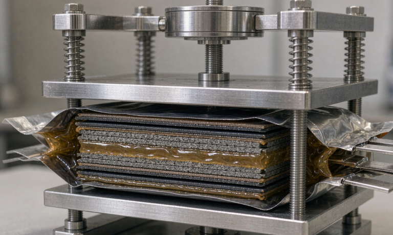
cause of lithium plating in the first formation cycle. - External stack pressure of 0.05–0.5 MPa in a pouch fixture. That is two orders of magnitude
less than an all-solid-state cell needs, which is precisely why a semi-solid architecture is
practical in a lithium battery pack today. - Formation: 0.05 C to 3.6 V, hold 6–10 h, then 0.1 C through the full window, degas, reseal.
Total formation time 60–100 hours including the wetting rest.
In-situ polymerisation versus pre-formed gel films
There are two production routes and they give very different cells.
Pre-formed film: you cast the gel electrolyte as a standalone membrane, then
laminate it between the electrodes. Pros: the film is measurable and inspectable before it ever meets
a cell, thickness control is easy, and you can reject bad lots cheaply. Cons: interfacial contact is
worse, so interfacial impedance is typically 20–40 Ω·cm² versus
8–15 Ω·cm² for the in-situ route, and you need a hot-press lamination step
at 60–90 °C.
In-situ polymerisation: you inject a low-viscosity precursor (monomer plus
cross-linker plus initiator plus salt) into a dry stacked cell, then polymerise with heat at
60–80 °C or UV. Pros: excellent conformal contact, no lamination step, and the precursor
wets like a liquid electrolyte. Cons: conversion is rarely complete — I target residual monomer
below 500 ppm — and any shrinkage during cure creates voids. Thermal-initiated routes with
AIBN or peroxide initiators also leave decomposition gases that must be removed in the degas step.
For a custom battery solution at low to medium volume, I nearly always recommend the in-situ route
because it avoids lamination tooling. For a high-volume automotive or aviation programme where yield
and traceability dominate, the pre-formed film wins.
How I validate a formulation before it reaches a customer
Four measurements tell me 90% of what I need to know, and every one of them is cheap:
- Ionic conductivity by EIS on a symmetric blocking cell
(SS | electrolyte | SS). I want 0.5–3 mS/cm at 25 °C, and I want the Arrhenius plot to be
linear from −20 °C to 60 °C with an activation energy of 0.15–0.35 eV. A kink in
that plot means a phase transition is hiding in your service range. - Li+ transference number by the Bruce–Vincent method: DC
polarisation at 10 mV on Li | electrolyte | Li with EIS before and after. A carbonate liquid
electrolyte gives 0.25–0.40; a well-designed semi-solid gel with anion-trapping groups or a
polymerised ionic liquid reaches 0.45–0.65. Higher t+ directly buys you rate
capability. - Oxidation onset by LSV at 0.1–1 mV/s on a stainless or aluminium working
electrode. I require the onset to sit at least 0.3 V above the cathode cut-off. For an NMC811 cell
charging to 4.2 V, that means onset no lower than 4.5 V vs Li/Li+. - Cell-level cycling with reference limits: 0.5 C charge and 1 C discharge at
25 °C should deliver 800–1,500 cycles to 80% of initial capacity for a graphite-anode
semi-solid cell, and 400–800 cycles for a silicon-blended or lithium-metal design. Anything
below 300 cycles means the interphase is unstable, and no amount of formation tuning will fix it.
Failure modes I see most often
- Aluminium corrosion at high voltage from LiTFSI or LiFSI without a passivating
co-salt. Symptom: capacity fade that accelerates after cycle 50, and a black deposit on the cathode
foil when you tear the cell down. - Gassing during formation from excess FEC or from residual moisture above
20 ppm. Symptom: a pillow pouch and a 5–10% capacity loss between formation and grading. - Dry spots at the separator interface from a gel with too high a yield stress.
Symptom: localised lithium plating that shows up as a capacity cliff after 100–200 cycles, not
as an early failure. - Ceramic filler agglomeration from insufficient dispersion. Symptom: a coating
that passes visual inspection but shows 2–3× the cell-to-cell DCIR spread. I specify a
three-roll mill or high-shear dispersion step and a laser-diffraction check with D90 below 5 µm.
Compliance, transport and what customers ask for
A semi-solid state battery is still a lithium battery in the eyes of every regulator. For
transport certification we run UN38.3 (T1–T8) on the cell and pack, IEC 62133-2 for portable
sealed cells and batteries, and IEC 62619 or UL 1973 for stationary and industrial applications. For
aviation and UAV integration, the pack additionally needs to satisfy the airworthiness authority’s
battery installation criteria and to carry documented abuse-test evidence — in practice that
means an external short, an overcharge to 1.5× the rated voltage, and a thermal ramp, all with
no fire and no case rupture.
The practical advantage of the semi-solid route here is real: with free liquid reduced by
50–80%, the nail-penetration and crush results improve measurably, and the venting behaviour is
far less violent. That is why a solid-state drone battery or a high-end drone battery pack for
inspection and mapping work is one of the most credible near-term applications.
Practical takeaways
If you take one thing from this guide, let it be that formulation is a systems problem. Conductivity,
viscosity, interfacial impedance and abuse behaviour pull against each other, and the winning recipe
is always a compromise that you validate on a real cell, at a real coating speed, in a real dry room.
Start with a PVDF-HFP or PMMA host at 40–60 wt% solids, run LiTFSI with 1–2 wt% LiDFOB to
protect the aluminium foil, add 5–15 wt% of a garnet or oxide filler, keep free liquid under
25 wt%, and hold the coating viscosity between 2,000 and 8,000 mPa·s. Then let the
cycle-life data tell you the truth.
Frequently asked questions
What is the difference between a semi-solid state battery and an all-solid-state battery?
A semi-solid cell still contains 10–30 wt% of a liquid or gel plasticiser inside a polymer
scaffold, giving ionic conductivity of 0.5–3 mS/cm at 25 °C and requiring only
0.05–0.5 MPa of stack pressure. An all-solid-state cell contains no liquid phase at all and
typically needs 10–50 MPa of external pressure plus a carefully engineered interlayer to keep
the electrode–electrolyte contact alive. That pressure requirement is the main reason
all-solid-state has not reached volume production.
Why is LiTFSI so popular in semi-solid electrolyte formulation?
Because it is thermally stable to above 350 °C, tolerant of residual moisture in the dry room,
and delivers the highest conductivity of the common lithium salts in polymer hosts. The trade-off is
that it does not passivate the aluminium cathode current collector above roughly 4.0 V, so it is
almost always paired with a small amount of LiDFOB, LiBOB or LiPF6.
How much ceramic filler should I add?
For ionic conductors such as LLZO or LATP, 5–15 wt% of the electrolyte fraction usually gives
the best balance of conductivity and mechanical strength. For non-conductive oxides such as
Al2O3 or fumed silica, 2–5 wt% is enough to raise the shear modulus and
scavenge HF. Beyond about 25 wt% total, the film becomes brittle and interfacial impedance climbs.
What viscosity should the gel be for slot-die or doctor-blade coating?
I specify 2,000–8,000 mPa·s at a shear rate of 10–100 s-1 at the
actual coating temperature, with a yield stress of 10–100 Pa and thixotropic recovery to 80% of
rest viscosity within 30–60 s. Always measure at coating temperature, not at 25 °C in the
lab, because a 15 °C rise can halve the viscosity.
How do I measure the lithium-ion transference number?
Use the Bruce–Vincent method: assemble a symmetric Li | electrolyte | Li cell, run EIS, apply
a small DC polarisation of about 10 mV until the current reaches steady state, then run EIS again and
combine the initial and steady-state currents with the initial and final interfacial resistances.
Liquid carbonate electrolytes land at 0.25–0.40; a good semi-solid gel reaches
0.45–0.65.
Can a semi-solid cell use a lithium-metal anode?
Yes, and this is where the architecture earns its keep: the higher shear modulus of the gel slows
dendrite propagation compared with a free liquid, and lithium-metal semi-solid cells have demonstrated
350–450 Wh/kg at cell level in pilot builds. The practical limits are cycle life, typically
400–800 cycles to 80%, and the need for tight stack-pressure control and very dry processing
below −50 °C dew point.
Which certifications apply to a semi-solid battery pack?
At minimum UN38.3 (T1–T8) for transport, IEC 62133-2 for portable sealed cells and batteries,
and IEC 62619 or UL 1973 for industrial and stationary use. Packs for aviation additionally need
documented abuse testing and an installation-level safety assessment accepted by the relevant
airworthiness authority. Because a semi-solid cell is still a lithium battery, none of these
requirements are reduced by the lower liquid content — only the test results tend to be
better.
How long does formation take for a semi-solid pouch cell?
Budget 12–48 hours of wetting rest, then 0.05 C to 3.6 V with a 6–10 hour hold, then
0.1 C through the full window, followed by degassing and resealing. Total elapsed time is typically
60–100 hours, roughly 30–50% longer than a conventional liquid cell because the gel needs
far more time to equilibrate inside the electrode pores.