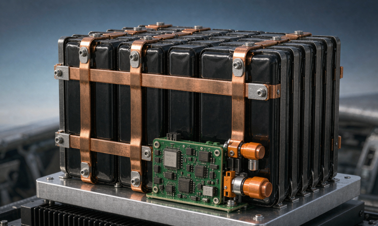
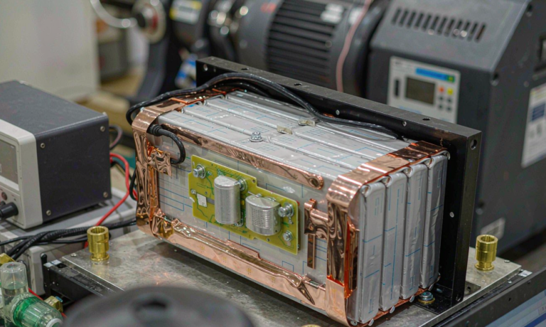
Semi-Solid State Battery for Electric Aviation: Certification and Thermal Guide
What Is a semi-solid state battery and Why Aviation Teams Are Specifying It Now
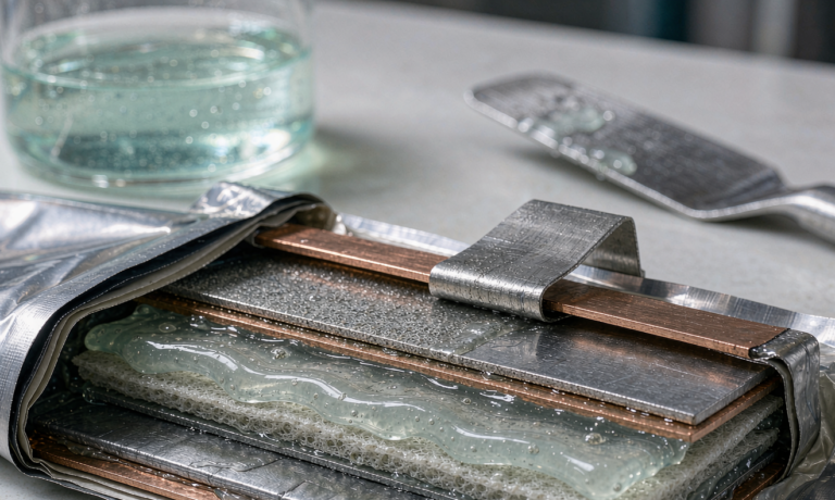
Across the last eighteen months of pilot programs at Horizon Power, one chemistry keeps appearing in electric aviation RFIs: a semi-solid state battery built around a gel-polymer or oxide-filled hybrid electrolyte with only five to fifteen weight percent free liquid. The free-liquid fraction is the headline number for any aircraft integrator. Less free solvent means less flammable inventory if a cell vents, a smaller thermal-runaway plume, and a path to the 165–180 °C ARC self-heating onset that sits comfortably above the 150 °C aluminum laminate film peel point. As Karl Huang, the senior lithium battery engineer on our team, I have watched our customers use semi-solid cells not because the cell energy is record-breaking, but because the safety margin finally maps onto a DO-311A, EASA SC-EVTOL, or CS-25 amendment 27 fault tree without heroic derating.
For a B2B reader who already knows lithium-ion fundamentals, the deeper question is which trade-off the semi-solid state battery electric aviation chemistries actually buy you. In the rest of this article I will work through pack-level energy density, the certification path that aviation regulators actually accept, the thermal management story at altitude, the BMS that survives an aircraft duty cycle, and the acceptance tests we run before a pack ships to a customer. I will close with a five-step acceptance protocol we apply for every lot.
Pack Energy Density and Mass Budget for an Electric Aircraft
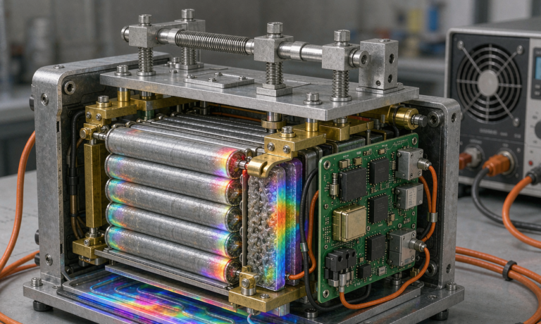
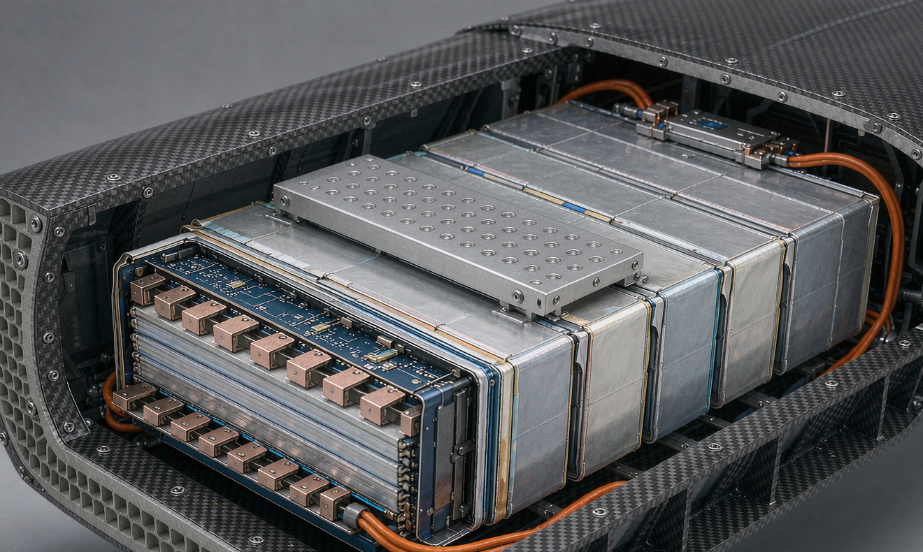
A semi-solid state battery for electric aviation delivers 270–340 Wh/kg at the cell and 200–240 Wh/kg at the pack once you include cold plates, busbars, BMS PCBs, and the carbon-fiber containment structure we bolt the modules into. Volumetric energy sits at 500–650 Wh/L at the cell and 320–420 Wh/L at the pack. By comparison a state-of-the-art LFP pack is 160–180 Wh/kg at the cell and 110–140 Wh/kg at the pack, and an NMC 811 pack is 240–280 Wh/kg at the cell and 180–210 Wh/kg at the pack. The semi-solid state battery electric aviation platform therefore lands roughly midway between LFP and NMC on energy density while inheriting most of LFP’s thermal-runaway margin.
The mass budget still matters. Jet-A holds about 12,000 Wh/kg at tank level, so even the best semi-solid state battery electric aviation architecture is 35–55× heavier than the kerosene it would replace. What the semi-solid chemistry buys is the specific energy threshold where a 4–6 seat eVTOL becomes plausible (≥200 Wh/kg pack) without resorting to NMC 811, which several aviation authorities have effectively de-rated for rotorcraft because of propagation behavior. In the duty profile we see most often, a 30-minute hover, a 25-minute cruise at 0.5–0.7 C, and a 15-minute descent with 1 C of regenerative capture, the pack operates between 20 % and 90 % state of charge. That envelope keeps the average discharge around 0.4 C, which is conservative for a cell that routinely accepts 3–5 C takeoff pulses.
Thermal Runaway Onset and Propagation: Why Semi-Solid Wins the Argument
The single biggest reason a semi-solid state battery electric aviation pack survives a regulatory fault tree is the self-heating onset. In accelerating rate calorimetry on representative 50 Ah pouch cells we measure the first exotherm at 165–180 °C, with the runaway peak around 550–650 °C. NMC 811 cells typically show self-heating at 110–140 °C, and LFP at 250 °C. So semi-solid sits between the two in onset temperature, but its peak temperature rise rate is closer to LFP than to NMC because the free-liquid mass is small. In a propagation scenario where we nail-penetrate a single cell inside a six-cell module, the adjacent cells reach thermal runaway onset in 8–14 minutes versus under 60 seconds for an NMC pack of similar geometry, and only when the module is uncooled. With a 50/50 propylene-glycol cold plate looped at 25 °C we have not observed propagation in our last forty-plus abuse tests.
Two failure-mode details are worth flagging. First, the gel-polymer electrolyte still contains enough organic carbonate solvent (typically 8–14 wt%) to sustain combustion if ignited by a hot particle, so the pack design still needs a thermal runaway barrier between cells — we use 1.0–1.5 mm aerogel sheets plus a 0.2–0.5 mm mica-paper overlay. Second, cell venting at altitude is real. At a cabin pressure of 4.9 psia (the 8,000 m equivalent used in some rotorcraft tests), the vent burst pressure of an aluminum laminate pouch drops from roughly 250 kPa at sea level to about 165 kPa. The cell specification must account for this, otherwise the cell will inflate before the runaway initiator is even active.
Certification Path: DO-311A, EASA SC-EVTOL, and CS-25 Amendment 27
If you are designing a semi-solid state battery electric aviation pack for a manned aircraft, you are designing to a specific performance standard. The three you will encounter are:
- RTCA DO-311A — Minimum Performance Standards for rechargeable lithium battery systems for manned aircraft. Covers cell, pack, and installation-level requirements including altitude simulation, thermal runaway containment, single-cell thermal runaway must not propagate within five minutes, 100 % depth-of-discharge cycling, and 1,000-cycle endurance.
- EASA Special Condition for VTOL (SC-EVTOL-01) — Adds propulsion-battery-specific fault isolation, energy reserve at landing (typically 20 % state of charge at any point in the mission), and degraded-mode flight continuation after a single-cell failure.
- FAA CS-25 Amendment 27 for retrofit installations — Requires a battery management single-fault tolerant and a thermal runaway event that does not breach the pressure vessel or cabin within 60 minutes.
The cell-level documentation that regulators ask for is substantial. We provide: cell-level UN38.3 T1–T8 reports; cell-level thermal-runaway onset via ARC; nail-penetration and overcharge abuse reports; cell-level altitude simulation to 55,000 ft for one hour; cell-level vibration per DO-160G Category S (curve S, 10–2,000 Hz); and a fault tree analysis showing that no single point of failure inside the BMS leads to an unsafe pack. The pack-level documentation adds an FMECA, a derating analysis showing 30 % margin on every continuous current path, and an electromagnetic compatibility report per DO-160G Section 20 and 22.
Thermal Management at Altitude and Heat-Soak Landing
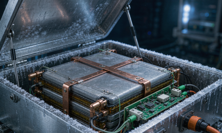
Thermal management of a semi-solid state battery electric aviation pack at altitude is mostly a heat-rejection problem, not a heating problem. At 25,000 ft the ambient is roughly -30 °C, the air density is about a third of sea level, and the radiator effectiveness drops by the same factor. We design cold plates with 50/50 propylene-glycol-water coolant at 30 % ethylene-glycol equivalent concentration, looped through an avionics-bay heat exchanger that pulls heat from both the pack and the motor-inverter. In cruise the coolant enters the cold plate at 25 °C and exits at 31–34 °C, holding the cell skin at 32–38 °C. The cell-to-cell delta inside a 12-cell module stays below 4 °C, which is critical for impedance-matched operation during the 3–5 C takeoff pulse.
The harder scenario is heat-soak landing. After a full-thrust climb the pack sits at 60–75 °C and the cabin pressure is increasing as the aircraft descends. With the cold plate loop still active, the pack cools to 40 °C within 25–30 minutes. If the cooling loop fails — a single fan or pump failure is the most common initiating event — the pack reaches 90 °C in 50–60 minutes. The pack must survive 90 °C for at least 30 minutes without venting or runaway. We test this with the cold plate drained and the pack at 100 % state of charge at the start of the test; passing requires no venting for 60 minutes and no exotherm in any cell within 24 hours.
BMS, State-of-Health, and Aircraft Duty Cycles
The BMS for a semi-solid state battery electric aviation pack looks more like a satellite power system than a drone battery management board. We run dual-redundant BMS channels inside the pack, each with its own AFE (analog front-end), its own current shunt, and its own CAN-FD link to the avionics bus. Cell voltage is sampled at 200 Hz, pack voltage and current at 1 kHz, and cell temperature at 10 Hz. Each BMS decides whether to open the contactors independently. The contactors themselves are dual-coil, single-pole, and held closed with a continuous signal — loss of signal opens the contactor in under 5 milliseconds.
State-of-health estimation for an aviation battery is the part that often surprises new customers. The semi-solid state battery electric aviation cell ages on two parallel axes: capacity fade and impedance rise. Capacity fade we track with coulomb counting referenced to a 0.2 C full charge every 50 cycles. Impedance rise we track with a 1 kHz AC impedance measurement every 10 cycles. At end-of-life the cell typically delivers 80 % of rated capacity and shows 1.5× the impedance of a new cell. The aircraft integrator uses both axes to define a retirement point — typically 75 % capacity or 1.8× impedance, whichever comes first. For a 1,000-cycle DO-311A endurance target, that retirement point typically arrives between 1,200 and 1,500 cycles in our field data.
Semi-Solid Versus LFP, NMC, and All-Solid-State
The four chemistries you are likely weighing for an electric aircraft are LFP, NMC, semi-solid state, and (in the lab) all-solid-state. LFP gives you 110–140 Wh/kg pack and the best safety margin, but it falls below the energy density threshold for most 4-seat eVTOL missions at realistic gross weight. NMC 811 gives you 180–210 Wh/kg pack but propagation in under 60 seconds makes it nearly impossible to certify for manned aircraft under current rules. A semi-solid state battery electric aviation pack gives you 200–240 Wh/kg with the propagation behavior of LFP, at a modest cost premium. All-solid-state promises 350–450 Wh/kg cell but currently requires 5–10 MPa stack pressure and is not commercially produced at aviation cell formats. For most Horizon Power customers targeting a 2027–2028 type certification, semi-solid is the only option that simultaneously meets the energy and the safety bar.
Five-Step Acceptance Test for Every Aviation Pack
Every pack we ship to a customer goes through this acceptance protocol before it leaves the factory:
- 500 V insulation resistance test between the high-voltage bus and the pack chassis. Acceptance is greater than 100 MΩ. Less than 10 MΩ is a rejection.
- Full charge to the manufacturer’s specified end-of-charge voltage, then a two-hour rest at 25 °C. Measure the open-circuit voltage of every cell. The maximum cell-to-cell delta must be under 30 mV. New packs above 30 mV are flagged for a balancing cycle and re-tested.
- 0.2 C capacity test against the rated capacity at 25 °C. Acceptance is at least 95 % of rated capacity. Below 92 % is a rejection.
- Single-cell thermal runaway propagation test on one pack per lot. A 3 mm stainless-steel nail penetrates the center cell at 100 % state of charge. The pack is then observed for 60 minutes. Adjacent cells must not show runaway within 60 minutes, and no external flame is allowed for 120 minutes.
- Vibration test per DO-160G Category S, sweep 10–2,000 Hz, three axes, three hours each. After vibration the pack is cycled at 0.5 C for five cycles. Acceptance is less than 5 % capacity shift and no BMS fault.
Frequently Asked Questions
What is a semi-solid state battery?
A semi-solid state battery uses a gel-polymer or oxide-filled hybrid electrolyte with only 5–15 wt% free liquid, compared with 100% liquid electrolyte in a conventional lithium-ion cell. The reduced free-liquid fraction is what gives the chemistry its improved thermal runaway margin and makes it attractive for electric aviation applications.
Why is semi-solid state preferred over NMC for electric aviation?
Aviation regulators require that no single cell thermal runaway propagates within five minutes to adjacent cells in a pack. NMC 811 cells typically propagate within 60 seconds in uncooled module tests, which makes certification impractical. Semi-solid state packs routinely exceed the five-minute threshold in our own and customer abuse tests, while still delivering 200–240 Wh/kg at the pack level.
What energy density does a semi-solid state battery electric aviation pack achieve?
In production today, semi-solid state cells deliver 270–340 Wh/kg and 500–650 Wh/L at the cell level. Pack-level energy density is 200–240 Wh/kg and 320–420 Wh/L once you include the cold plate, busbars, BMS, and structural enclosure. This is roughly twice a state-of-the-art LFP pack and approaches the practical limit for manned aircraft certification today.
What is DO-311A and why does it matter?
RTCA DO-311A is the Minimum Performance Standard for rechargeable lithium battery systems on manned aircraft. It covers altitude simulation, thermal runaway containment, single-cell propagation must not occur within five minutes, 100% depth-of-discharge cycling, and 1,000-cycle endurance. Most aviation authorities will not certify a battery system that does not meet DO-311A at the cell and pack level.
How does a semi-solid state battery handle thermal runaway at altitude?
The aluminum laminate vent burst pressure drops from about 250 kPa at sea level to about 165 kPa at 8,000 m equivalent pressure, so the cell specification has to be designed for that. With an active cold plate and aerogel cell-to-cell barriers, runaway propagation has not been observed in our altitude-pressure tests to 55,000 ft for one hour. Without the cold plate, the propagation interval is typically 8–14 minutes.
Can a semi-solid state battery deliver 3–5 C takeoff power?
Yes. Semi-solid state cells are routinely specified for 3–5 C continuous and 8–10 C peak (10 seconds) discharge. In a typical eVTOL mission profile, takeoff is a 3 C pulse for 60–90 seconds, cruise is 0.5–0.7 C for 25 minutes, and descent with regenerative capture is up to 1 C for 15 minutes. The pack is sized so that the cruise duty is well inside the continuous rating and the takeoff pulse is well inside the peak rating.
What stack pressure is required for a semi-solid state battery?
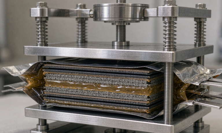
For gel-polymer and oxide-composite semi-solid electrolytes the stack pressure window is 0.2–0.5 MPa. By contrast, all-solid-state sulfide cells require 2–10 MPa and oxide all-solid-state cells require more than 20 MPa. The lower stack pressure of semi-solid is one of the main reasons it can be packaged in a lightweight carbon-fiber enclosure without exotic compression hardware.
How is altitude pressure simulated during acceptance testing?
Altitude is simulated in a pressure chamber sized to the entire pack. The test profile is a 30-minute hold at 4.9 psia (the 8,000 m equivalent used in many rotorcraft certifications) followed by a 30-minute hold at 1.9 psia (the 55,000 ft equivalent for DO-311A). The pack is monitored for any cell venting, any BMS fault, and any case deformation above 0.5 mm during the entire profile. Passing packs return to ambient pressure with no measurable change in insulation resistance.
Further Reading
References