Lithium Battery Cell Balancing: Passive vs Active Methods
Every lithium battery pack I have torn down after a field failure tells the same story in the data log: the cells did not fail together. One cell drifted, the BMS cut on that cell, and the other ninety-eight percent of the pack sat there unused. Cell balancing is the discipline that decides whether a pack delivers its nameplate capacity for five years or starts losing range in eighteen months. It is also one of the most oversold features in the industry, so this article separates what balancing can fix from what it cannot, and gives you the numbers I use to choose between passive and active topologies.
Why Cells in a lithium battery Pack Drift Apart
Series cells carry identical current, but that is where the similarity ends. No two cells leave the production line with the same capacity, and no two cells live the same thermal life. I group the causes into four buckets, because each one calls for a different response.
- Initial manufacturing spread. Even on a tightly binned line, capacity spread of 0.5 to 1.5 percent and internal resistance spread of 3 to 8 percent is normal at the cell level. Buying matched cells reduces it; it does not remove it.
- Self-discharge differences. Typical lithium cells self-discharge 1 to 3 percent per month at 25 degrees C, but the spread between the best and worst cell in a batch can be twice that. Over a six-month standby period, that alone produces tens of millivolts of divergence.
- Coulombic efficiency differences. A cell at 99.94 percent coulombic efficiency versus one at 99.90 percent diverges by roughly 0.4 Ah for every 1,000 Ah cycled. On a 100 Ah pack that is measurable drift within a few hundred cycles.
- Temperature gradient. This is the dominant one in the field. A 5 degree C persistent gradient across a pack can double the ageing rate of the hot cell. That cell loses capacity faster, its resistance rises faster, it runs hotter still, and the divergence accelerates. Balancing does not fix this. Thermal design does.
The consequence is arithmetic, not opinion. On discharge, the pack stops at the weakest cell. On charge, it stops at the strongest cell. Usable capacity is therefore reduced by roughly the mismatch, not half of it. A 2 percent mismatch in a 100 Ah pack costs you about 2 Ah on every single cycle, and that loss compounds as the mismatch grows.
What Balancing Actually Does, and What It Cannot
Balancing moves the cells to a common state of charge. It does not increase the capacity of a weak cell, it does not reverse capacity fade, and it does not repair a cell with a growing internal resistance. I have had customers ask for active balancing to “recover” a pack that had already lost 12 percent capacity. Nothing in the BOM will do that. What balancing does is stop a healthy pack from wasting the capacity it still has.
There are two reference points. Top balancing aligns all cells near full charge, which maximizes usable discharge energy and is the right default for traction and cycling applications. Bottom balancing aligns cells near empty, which maximizes usable charge acceptance and is occasionally used in storage systems that rarely reach full charge. Most commercial BMS designs top balance, and unless you have a specific reason, you should too.
One more limitation that catches people out: balancing is only valid when voltage is a reliable proxy for state of charge. In the middle of an LFP plateau the open circuit voltage slope can be as flat as 1 to 5 millivolts per percent of state of charge, so a 30 millivolt delta can correspond to almost nothing or to several percent, depending on where you are on the curve. This is why a good algorithm only balances near the top of charge, with current below roughly 0.05C.
Passive Balancing: Bleed Resistors
Passive balancing is the dominant approach and for good reason. Each cell has a resistor and a switch, usually a MOSFET integrated into the analogue front end. When a cell is high, the switch closes and the excess energy is burned as heat.
The engineering is all in the thermal budget. At 3.6 volts across a 33 ohm resistor, you get about 109 milliamps of bleed current and roughly 0.39 watts per cell. Most designs I specify run 50 to 150 milliamps, so 0.2 to 0.5 watts per channel. Multiply that by 16 channels in a sealed enclosure and you have added a heater to a battery module, which is the last thing a battery module needs. I always require a layout review confirming the resistor cluster is not thermally coupled to the cell cans or to the thermistor used for charge control.
The practical limit is time. Consider a realistic case: a 100 Ah lithium battery pack with 3 percent cell-to-cell capacity mismatch, which is 3 amp-hours of divergence. At 120 milliamps of bleed current, correcting that takes about 25 hours of active balancing. If your duty cycle gives you a one-hour top-of-charge window per day, you need 25 days to converge, and in the meantime the mismatch is still growing from thermal gradients. Passive balancing works well when the drift rate is slow and the initial mismatch is small. It does not work when you need convergence in one charge cycle.
Active Balancing: Moving Charge Instead of Burning It
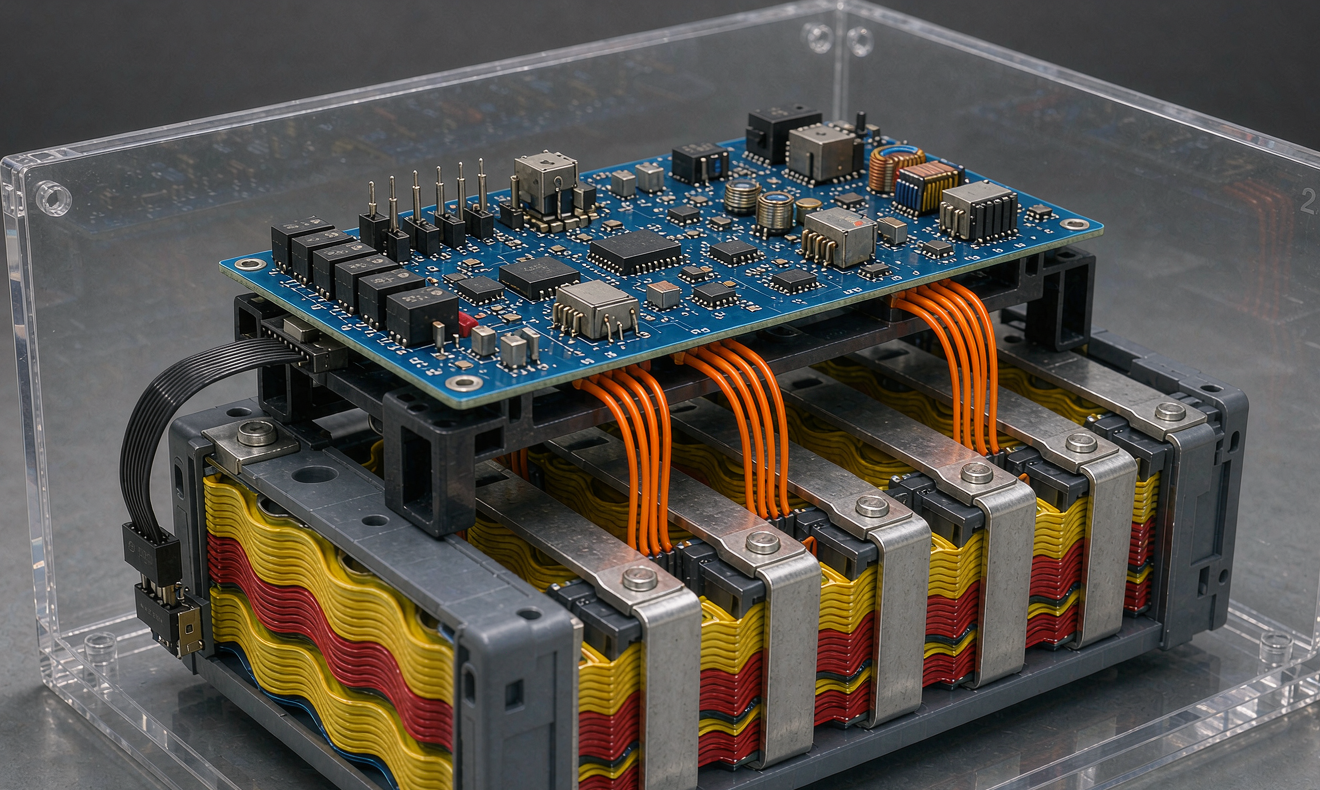
Active balancing transfers energy between cells instead of dissipating it. Three topologies cover nearly everything on the market.
Switched Capacitor
A capacitor is switched between adjacent cells, shuttling charge down the stack. Simple and low stress, but the transfer current falls as the voltage difference shrinks, so convergence near the end is slow. Transfer efficiency is typically 75 to 85 percent, and the current is usually 0.5 to 2 amperes.
Inductor or Transformer Based
An inductor or a multi-winding transformer moves energy either cell to cell or cell to pack. This supports higher current, commonly 1 to 5 amperes, with efficiencies of 85 to 92 percent. It is the topology I see most often in larger storage racks and in commercial vehicle packs.
Bidirectional DC-DC, Module to Pack
Each module has a small bidirectional converter that takes energy from the whole pack and pushes it into the weakest module, or the reverse. Efficiency can reach 90 to 95 percent because the conversion is only one stage and the voltage ratio is modest. The limitation is granularity: it fixes module-level mismatch, not cell-level mismatch inside the module.
Using the 3 amp-hour mismatch case from above, a 2 ampere active balancer converges in roughly 1.5 hours instead of 25. That is the entire value proposition, and it is real. What you pay is BOM cost, board area, software complexity and an electromagnetic emissions problem that did not exist before.
- BOM cost. Passive balancing adds roughly 0.5 to 2 US dollars per cell. Active balancing adds 5 to 25 US dollars per cell depending on topology and current rating, before the extra engineering.
- Efficiency. Passive is zero percent by definition; the energy leaves as heat. Active returns 75 to 95 percent of the transferred energy to the pack.
- Emissions. A switching balancer at several hundred kilohertz inside a metal enclosure is a conducted and radiated emissions source. On automotive programs you will be measured against CISPR 25; on industrial equipment, against IEC 61000-6-3 and 6-4. Budget filtering and a pre-compliance scan.
- Failure modes. Passive balancing fails safe: an open resistor simply stops balancing. Active balancing has more ways to fail, including a stuck switch that slowly discharges a cell. I require an independent hardware watch on cell voltage deviation, not just firmware limits.
How I Choose Between Passive and Active
I use four gates. If the answer is yes to three or more, active balancing pays for itself.
- Is the mismatch large or fast? Cells from a wide bin, a second-life pack, or a pack with a known thermal gradient all push toward active.
- Is the top-of-charge window short? Fast-charge duty cycles and opportunity charging leave passive balancing too little time.
- Is the pack large? Above roughly 10 kilowatt-hours, the absolute energy lost to heat and the value of recovered capacity both grow. Below about 2 kilowatt-hours, active rarely pencils out.
- Is downtime expensive? In a system where a service call costs more than the balancer, I specify active even when the electrical case is marginal.
The reverse cases matter just as much. For a well-matched LFP pack under 5 kilowatt-hours with a daily full charge and a modest thermal design, passive balancing is genuinely the better engineering choice. It is cheaper, it has no switching noise, it has fewer components to fail, and it is easier to certify under IEC 62619 and UL 1973 because there is less to analyse. I have talked customers out of active balancing more often than into it.
Chemistry also plays a role. LFP has a flat voltage curve, so voltage-based decisions are noisy in the mid-range, and the long cycle life gives small mismatches thousands of cycles to grow. NMC has a steeper open circuit voltage slope, which makes voltage-based balancing more reliable, but its shorter cycle life makes divergence more dangerous. In both cases the algorithm should be gated on voltage window, current and temperature, not voltage alone.
Implementation Details That Decide Whether It Works
The topology matters less than the details. Here is what I put in a specification before signing off on any custom battery solution.
- Measurement accuracy. Modern analogue front ends such as the LTC6813-class and BQ7695x-class parts specify cell voltage accuracy in the range of plus or minus 2 to 5 millivolts over temperature. If your balancing threshold is 10 millivolts and your measurement error is 5 millivolts, you are balancing on noise. Set the threshold at least three times the worst-case error.
- Kelvin sensing. Sense leads must be separate from the power path. A 2 milliohm contact resistance at 50 amperes produces a 100 millivolt error, which is an order of magnitude larger than the signal you are trying to measure. Every sense lead also needs a fuse or a current-limiting resistor, because a shorted sense wire takes out the front end.
- Gating. Balance only when all of the following are true: minimum cell voltage above a chemistry-specific threshold, charge current below about 0.05C, and all cell temperatures inside 15 to 45 degrees C. Balancing at temperature extremes or during high current moves you further from convergence, not closer.
- Duty cycle and thermal derating. For passive balancing, specify the resistor continuous rating with at least 2x margin and define a maximum simultaneous channel count. I have seen boards where all 16 channels could energize at once inside a sealed IP66 enclosure.
- Logging. Record the per-cell delta at rest, the maximum delta during discharge, and cumulative balanced amp-hours per channel. Those three trends tell you within a few weeks whether you have a balancing problem or a cell problem.
Acceptance Tests Before Shipment
Balancing is easy to claim and hard to verify, so I write the tests into the purchase order.
- Convergence test. Deliberately unbalance the pack by 3 percent state of charge, then run the normal charge profile and time the convergence to under 30 millivolts delta. Passive designs will need many cycles; that is acceptable if it was agreed up front, but it should be measured, not assumed.
- Thermal imaging. Run balancing at maximum duty for 30 minutes in a 45 degree C chamber. Any balancing resistor or converter above the cell temperature limit is a design defect.
- Rest delta. After a 2 hour rest, cell-to-cell delta should stay under 30 millivolts. A delta that only appears under load is not a balancing problem, it is a connection resistance problem.
- Failure injection. Short a sense lead and open a balance channel, then confirm the BMS reports a fault and does not silently continue charging.
One field caution to finish on. If cumulative balanced amp-hours on a single channel keeps climbing month after month, you do not have a balancing problem. You have a cell that is losing capacity or developing an internal short, and no amount of balancing current will fix it. Pull that module before it takes the pack with it.
Frequently Asked Questions
What is the difference between passive and active cell balancing in a lithium battery?
Passive balancing burns excess charge from the highest cells through bleed resistors, typically at 50 to 150 milliamps, and dissipates the energy as heat. Active balancing transfers charge between cells or between a module and the pack using capacitors, inductors or DC-DC converters, at 0.5 to 5 amperes, returning 75 to 95 percent of the energy to the pack. Passive is cheaper and simpler; active converges far faster.
When is active balancing worth the extra cost?
When mismatch is large or fast-growing, when the charge window is short, when the pack exceeds roughly 10 kilowatt-hours, or when a service call costs more than the balancer. For a well-matched pack under 5 kilowatt-hours that receives a full charge daily, passive balancing usually remains the better engineering and commercial choice.
Does cell balancing restore lost capacity?
No. Balancing equalizes state of charge between cells. It cannot recover capacity lost to ageing, it cannot repair a cell with rising internal resistance, and it cannot reverse lithium plating or SEI growth. If a pack has genuinely lost 10 percent capacity, the fix is cell or module replacement, not a better balancer.
Why is balancing unreliable on LFP packs?
LFP has a very flat open circuit voltage curve, often 1 to 5 millivolts per percent state of charge in the plateau, so voltage is a poor proxy for state of charge in the mid-range. Balancing should be gated to the top of charge with current below about 0.05C, where the curve steepens and the voltage signal becomes meaningful.
How much balancing current do I actually need?
Start from the mismatch you expect, not from a datasheet. A 3 amp-hour mismatch on a 100 Ah pack takes about 25 hours to correct at 120 milliamps, or roughly 1.5 hours at 2 amperes. Divide your expected mismatch by your available top-of-charge window and add margin for continuing drift.
Can balancing fix a temperature gradient problem?
No. A persistent 5 degree C gradient roughly doubles the ageing rate of the hot cell, which increases mismatch faster than any balancer can remove it. Balancing treats the symptom; the cure is a thermal design that removes the gradient through cell spacing, cold plate layout, or airflow.
What balancing threshold should I set in the BMS?
Set it at least three times the worst-case measurement error of the analogue front end. With typical accuracy of plus or minus 2 to 5 millivolts over temperature, a start threshold of 20 to 30 millivolts with a stop hysteresis around 10 millivolts is realistic. A 10 millivolt threshold on a 5 millivolt error budget produces balancing on noise.
Do IEC 62619 or UL 1973 require a specific balancing method?
Neither standard mandates passive or active balancing. Both require that the control system keep cells within the manufacturer’s specified operating limits and that single-fault conditions do not lead to a hazardous outcome. Active balancing adds switching circuitry that must be analysed in that single-fault review, which is one reason simpler passive designs can be easier to certify.
Further Reading
References