Semi-Solid State Battery Moisture and Contamination Control
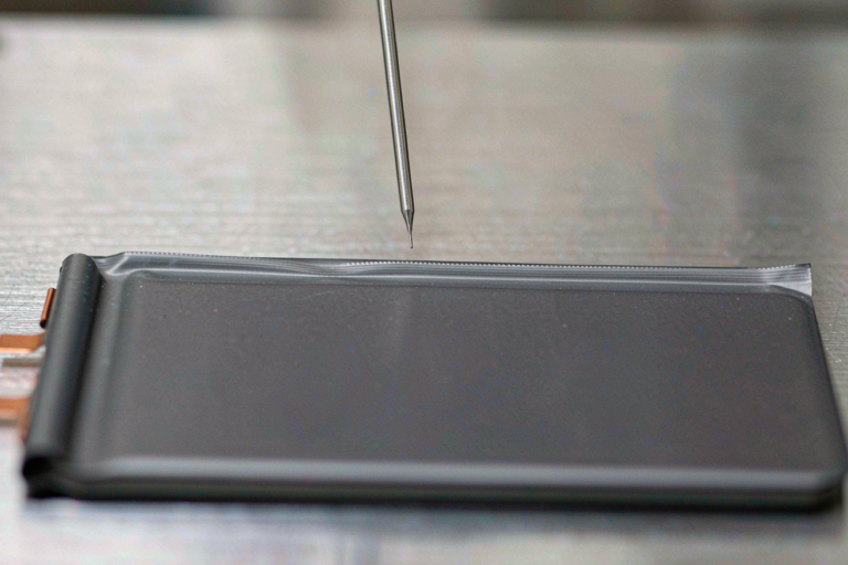
Most of the semi-solid state battery failures I have been asked to autopsy in the last four years were not caused by a bad chemistry. They were caused by water and particles that entered the cell long before anyone cycled it. A gel or quasi-solid electrolyte carries far less free liquid than a flooded cell, so it has almost no buffer against trace moisture. And because the electrolyte layer is thin, a particle that would have been harmless in a conventional jelly roll can bridge an interface and short it. Moisture and contamination control is therefore a design discipline, not a housekeeping task.
Why Moisture and Particles Share the Same Failure Path
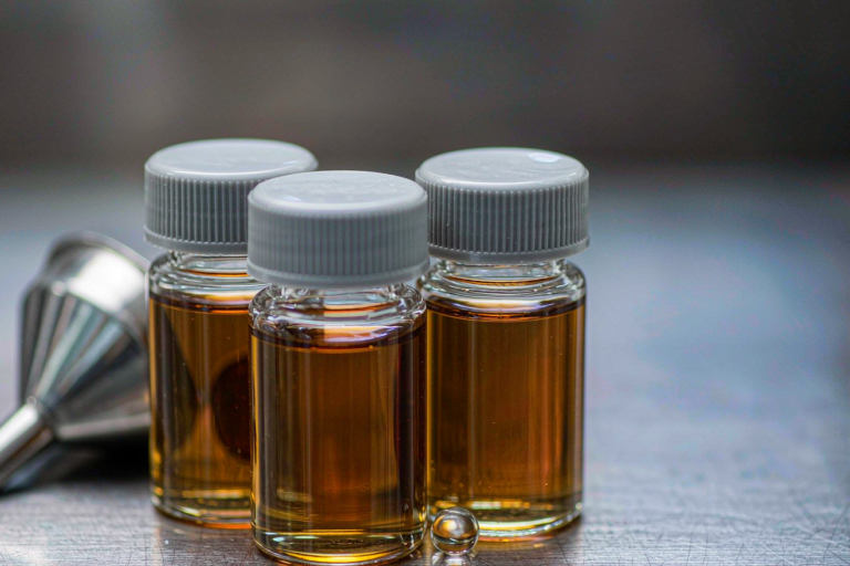
In a flooded lithium battery, the electrolyte volume is generous. A few hundred parts per million of water get absorbed, a little hydrofluoric acid forms, and the cell still performs acceptably for years. A semi-solid cell might hold 10 to 20 weight percent liquid phase inside a polymer or gel host. The same absolute amount of water represents a much larger fraction of that liquid pool, and the gel matrix can hold water against the electrode surfaces where it does the most damage.
Particles work in the opposite direction but toward the same result. Our electrolyte layer in a semi-solid pouch is often 15 to 30 micrometers thick. A 20 micrometer stainless steel fragment is therefore not a cosmetic defect, it is a potential through-thickness bridge. Once embedded, the metal dissolves and re-deposits under the field, forming the nucleus of a lithium dendrite. The cell does not fail immediately. It fails as elevated self-discharge, then as a soft short, then as a thermal event.
That is why we treat both variables as one control problem. Water attacks the salt and the interfaces chemically. Particles attack the interfaces mechanically and electrochemically. Neither shows up in a capacity check at the end of the line, which is exactly why both need to be controlled upstream.
The Water Ledger Inside the Cell, Not Just the Assembly Room
Dry room engineering gets most of the attention, and dew point is the headline number for a reason. But the room is only one line in the ledger. What matters at the end of the day is the total water mass that ends up inside the sealed pouch.
Building the Water Budget
Here is the arithmetic we use. A typical semi-solid pouch in our drone and industrial programs carries roughly 40 grams of coated electrode. If that electrode leaves the dryer at 300 parts per million water, it contributes 12 milligrams of water. Add separator at 200 parts per million, gel precursor solution at 20 parts per million, and the surface film on foils and tabs, and a realistic total sits between 15 and 25 milligrams.
Now convert that to chemistry. One mole of water consumes one mole of lithium hexafluorophosphate and releases two moles of hydrogen fluoride. Fifteen milligrams of water is 0.83 millimoles, which consumes about 127 milligrams of salt and liberates roughly 33 milligrams of hydrogen fluoride. In a cell whose salt inventory may only be a few grams, that is meaningful. The hydrogen fluoride then attacks the cathode surface, dissolves transition metals, and those metals migrate to the anode where they poison the solid electrolyte interphase. Self-discharge climbs, capacity fades faster, and gas builds up.
Where the Numbers Come From
We specify incoming powder at 200 to 600 parts per million depending on chemistry, hard carbon at 300 to 800, separator below 200, and gel precursor below 20. Electrode moisture is verified by coulometric Karl Fischer titration with oven extraction at 130 to 180 degrees Celsius on 1 to 2 gram samples. Battery grade salt is held below 20 parts per million water and below 50 parts per million hydrogen fluoride by certificate of analysis. The budget is recalculated every time a material or a dryer recipe changes, because a 100 part per million shift in cathode moisture is roughly 4 milligrams of water, which is not trivial when your total allowance is 25.
Particle Sources We Actually Chase on the Line
Every contamination investigation I have run ended at one of four sources. None of them were exotic.
Metallic Burrs from Slitting and Punching
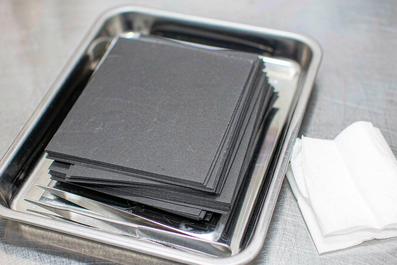
Slitting blades wear. At the start of a blade campaign, burr height on a coated electrode runs 2 to 4 micrometers. Push the same blade to 350 kilometers of web and we have measured 10 to 14 micrometers. That is the threshold where a burr can penetrate a thin gel electrolyte layer under stack pressure. We set an internal limit of 5 micrometers and verify it on 20 samples per shift with a cross-section under a measuring microscope. Blade change intervals in our lines are based on linear meters, not calendar time, and the interval is shortened for chemistries with harder or more abrasive coatings.
Weld Spatter and Tool Wear
Laser welding of tabs and current collectors generates spatter in the 5 to 50 micrometer range that lands on the cell body. We extract it with local fume extraction at the weld head, then wipe the fixture with a lint-free polyester wipe every four hours. Tooling is a quieter problem. Steel tweezers, suction cups and guide rollers shed particles as they wear, so we use ceramic tipped or coated tooling in the assembly zone and log tool replacements. A worn roller can distribute metal dust across an entire shift of production.
Fibers, Powder Residue and Changeover Carry-Over
Fibers come from garments, wipes and packaging. In an ISO Class 7 zone we use coveralls with a bound hood, nitrile gloves rather than powdered latex, and wipes that are specified for the class. Powder residue is a chemistry problem rather than a cosmetic one, because cross-contamination between a hard carbon anode line and a graphite line changes the kinetics, and residue from a cathode powder can carry sodium or transition metals into the wrong electrode. We isolate powder handling from assembly, hold the assembly zone at 5 to 15 pascals of positive pressure, and define a documented changeover with a verified wipe test before the next product starts.
Cleanroom Class, Zoning and Changeover Discipline
I do not believe every square meter of a semi-solid line needs the same class. Overbuilding is expensive and does not buy much. What we zone is risk.
- Coating, drying and calendering stay outside the controlled area, separated by an airlock.
- Electrode cutting, stacking and tab welding run at ISO Class 7, with local protection at the cut edge.
- Gel precursor preparation and filling run at ISO Class 6 to 7 with the lowest dew point on the site.
- Sealing and final assembly run at ISO Class 7 with positive pressure relative to the corridors.
Particle monitoring is continuous at the filling station and quarterly for the whole zone per ISO 14644-1, with alarm limits set at 50 percent of the class limit so that drift is caught before the class is breached. Changeover between products gets its own checklist: purge and wipe of filling lines, verified wipe test on the tooling, new filters where the product chemistry differs, and a signed record before the first cell is built.
Detection and Release Testing Before the Cell Is Sealed
Chemical methods catch what the eye cannot. Our standard release package for a semi-solid cell includes the following.
- Coulometric Karl Fischer on electrode samples, oven extraction, limit 300 parts per million.
- Ion chromatography on an aqueous extract of electrode and separator, watching fluoride, chloride and sulfate.
- Inductively coupled plasma analysis for iron, chromium, nickel, copper and zinc, with individual limits between 1 and 5 parts per million.
- Liquid particle counting on the gel precursor and the electrolyte, evaluated against a cleanliness code rather than a raw count.
- Burr inspection on cut electrodes each shift, cross-section and measuring microscope.
- Insulation resistance and withstand voltage on assembled modules, typically 500 volts direct current with a minimum of 100 megohms.
The last screen is self-discharge grading, and it is where contamination finally becomes visible. Cells rest for 24 to 72 hours after formation, and we track the open circuit voltage slope rather than a single reading. Our internal limit is a slope below 0.05 millivolts per hour, and we look at the distribution, not the average. A batch with a clean average and a heavy right tail is a contamination batch, and the tail is what reaches customers.
What to Ask a Semi-Solid State Battery Supplier About Moisture and Contamination
Almost every supplier will claim a minus 40 degrees Celsius dry room, and almost all of them will be telling the truth. The question is whether the room specification reaches the product. Ask for continuous dew point and particle data from the filling station, not a quarterly certificate. Ask for the last six months of electrode Karl Fischer results as a distribution. Ask what the burr limit is, how it is measured, and what the blade change interval is based on. Ask for one example of an out-of-specification batch and the disposition record that followed it, because a supplier that has never rejected a batch is either lucky or not measuring.
Also ask who owns the water budget. In our programs it is a single named process engineer with authority to stop the line, and the budget is a live document that is recalculated on every material or recipe change. Under UN 38.3 the cell still has to pass transport testing, and under IEC 62619 and UL 1973 the module has to demonstrate its safety behavior, but those tests only verify that the contamination control worked. They do not substitute for it.
Frequently Asked Questions
How much moisture is acceptable in a semi-solid state battery cell?
We work to a total internal water budget of 15 to 25 milligrams per cell, which translates to electrode moisture below 300 parts per million, separator below 200, and gel precursor below 20. The exact allowance depends on the salt inventory, because the damage scales with how much of the salt the water can consume.
Why is a semi-solid cell more sensitive to moisture than a conventional lithium battery?
Because it holds much less free liquid electrolyte. A flooded cell can absorb and tolerate trace water over a long service life, while a gel or quasi-solid host has a small liquid pool and holds water near the interfaces, so the same absolute amount of water does far more chemical damage.
Which contamination source causes the most field failures?
Metallic burrs from slitting and punching. They are small enough to pass visual inspection, they sit exactly at the electrode edge where the field is concentrated, and the resulting defect appears as rising self-discharge weeks or months later rather than as an immediate failure on the line.
What cleanroom class does a semi-solid state battery line need?
ISO Class 7 for cutting, stacking, welding, sealing and assembly, and ISO Class 6 to 7 at gel precursor preparation and filling, per ISO 14644-1. Coating and drying can stay outside the controlled area behind an airlock, which keeps the cost sane without exposing the sensitive steps.
How do you detect particle contamination before the cell is sealed?
Through a combination of liquid particle counting on the electrolyte, burr inspection on cut electrodes, ion chromatography for dissolved metals, and insulation resistance testing on modules. Every method has a blind spot, which is why we run all of them rather than relying on any single screen.
Can contamination control be relaxed once a battery design is qualified?
No, and this is the most common mistake I see. Qualification testing under UN 38.3, IEC 62619 or UL 1973 proves the process worked on the samples submitted. Any change of material source, dryer recipe or blade supplier resets the water and particle budget and requires re-verification, not a paper update.
Further Reading
References