Sodium-Ion Battery Calendering and Porosity Control
Sodium-ion cells ask the calender to do something lithium-ion never asked of it. The hard carbon anode stores most of its sodium in pores rather than between graphene layers, so every micrometer you compress out of that coating is capacity you cannot recover. I have set roll gaps on both chemistries, and the failure mode differs: on graphite you fight binder migration and foil wrinkling, while on hard carbon you fight the material’s own springback and the collapse of the closed pores that carry the low-voltage plateau. This is the setup I would run today if a customer asked me to commission a sodium-ion electrode line.
Why Sodium-Ion Electrodes Tolerate Less Compaction
Start with volume. Hard carbon has a true density of roughly 1.45 to 1.55 g/cm3; graphite sits near 2.26 g/cm3. For the same areal capacity you must deposit far more coating mass, which means a thicker wet layer and a thicker dry layer. A sodium-ion anode that delivers 3.0 mAh/cm2 is routinely 90 to 130 micrometers thick before calendering, where a graphite anode carrying the same charge might be 70 to 90 micrometers.
Then add the voltage penalty. A typical sodium-ion cell runs at a nominal 3.1 to 3.2 V with a 4.0 V cut-off, against 3.6 to 3.7 V for a lithium-ion cell with a layered oxide cathode, so matching pack energy pushes you toward higher areal loading. Thicker electrodes put the calender in charge of a larger share of the cell’s rate capability, because porosity and tortuosity after compaction decide how fast sodium ions move through the coating.
Aluminum on both sides changes the mechanics
Sodium does not alloy with aluminum, so a sodium-ion cell can use aluminum foil for the anode current collector instead of copper. That removes the 0 V transport restriction, cuts cost, and eliminates copper dissolution as a failure mode. It also gives you a softer substrate. Battery-grade aluminum foil in the 1N30 or 1235 alloys runs a yield strength of roughly 40 to 70 MPa, against 250 to 350 MPa for the copper foil used in a graphite anode. Soft foil wrinkles, curls, and stretches more readily under the same nip load, and it work-hardens less, so roll gaps drift out of tolerance faster between shim adjustments.
Hard Carbon Springback and the Closed Pores You Cannot Get Back
Hard carbon springs back more than graphite. Graphite anodes recover about 1 to 3 percent of their compressed thickness after the nip, while hard carbon recovers 3 to 7 percent depending on particle morphology, binder content, and roll temperature. If you set the roll gap to produce your final target thickness, you will over-compress the coating by that springback margin and land well below your intended density.
Measure thickness 30 to 60 seconds after the web leaves the nip, at a defined web tension, and use that number for control; I hold a fixed 40-second delay at the gauge on sodium lines. Set the gap for the un-recovered thickness, not the target.
Why over-compaction costs you capacity, not just rate
In hard carbon, the flat plateau below about 0.1 V versus Na/Na+ supplies roughly 55 to 70 percent of the reversible capacity. That plateau comes from sodium filling closed pores and adsorbing at defect sites, not from intercalation between layers. Those closed pores are collapsible. Push the electrode past its optimum density and you close pore mouths, so the plateau shortens and the first-cycle efficiency that looked fine on a lightly calendered lab cell drops by three to six points on the line. This is the most common mistake I see when a sodium-ion line is commissioned with lithium-ion compaction targets.
Target Porosity by Electrode and Duty Cycle
Porosity here means open porosity available to the electrolyte, calculated from geometry. The working windows I use for water-based sodium-ion electrodes are wider than their lithium counterparts, because hard carbon needs breathing room and polyanionic cathodes are brittle.
- Hard carbon anode: 32 to 38 percent porosity, density 1.05 to 1.25 g/cm3.
- Layered oxide cathode (O3 or P2): 26 to 32 percent. Softer particles, more prone to surface damage and moisture uptake.
- Polyanionic cathode (NVP, NASICON family): 30 to 36 percent. Hard, brittle particles with a carbon coating that compresses and carries much of the load.
- Prussian white cathode: 28 to 34 percent with the gentlest schedule, because the material is soft and moisture sensitive.
For high-rate duty such as a two-wheeler pack or a fast-charge telecom rectifier, take the upper half of each window; for slow-cycling stationary duty the lower half buys energy density and better particle contact without hurting rate. On a 3.0 mAh/cm2 hard carbon anode, moving from 36 percent to 31 percent porosity typically costs 8 to 12 percent of the 2C capacity while adding about 4 percent to cell energy.
Roll Temperature, Nip Load, and Pass Schedule
Sodium-ion electrodes are almost always water-processed with CMC and SBR, and the binder system sets the practical temperature window. I run hot calenders between 60 and 90 degrees Celsius on the roll surface. Warm rolls soften the binder film, which lowers springback and improves adhesion to the aluminum foil. Above roughly 100 degrees Celsius, SBR can migrate to the surface and form a tacky film that blocks on the unwind and produces shiny patches with poor electrolyte wetting.
Hard numbers I use on the line
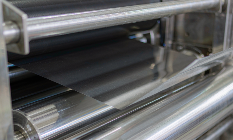
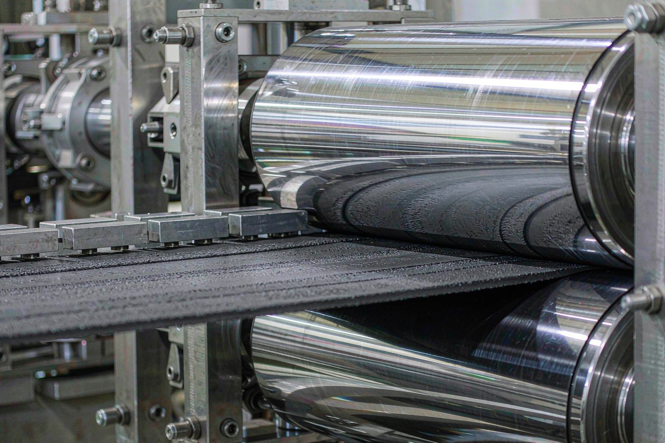
Nip linear force runs 150 to 400 N/mm for a hard carbon anode at 90 to 130 micrometers dry thickness, against 100 to 300 N/mm for a comparable graphite anode. Roll diameter sits between 400 and 600 millimeters, with crowned or anti-deflection rolls so that the center-to-edge thickness variation stays under 2 micrometers across a 300 millimeter web. Roll hardness is 60 to 70 on the Shore D scale and surface roughness is kept below 0.2 micrometers Ra.
Use two passes, not one: the first takes 60 to 75 percent of the total thickness reduction, the second trims to target and irons out cross-web variation. A single hard pass causes differential densification through the coating depth, leaves a dense skin over a loose bulk, and produces the edge cracking that shows up two shifts later. Line speed between 30 and 60 meters per minute is normal; slower speeds mean longer dwell in the nip and therefore more densification at the same force, useful for thick polyanionic cathodes.
The Defects I Reject, and What Each One Tells Me
Calender defects are diagnostic, not random; six patterns cover almost everything I see.
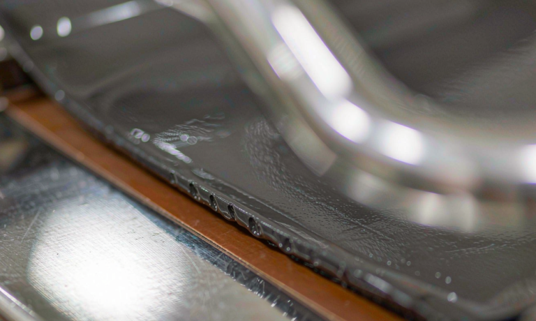
- Orange peel or mottled gloss: over-compaction, often combined with hard agglomerates or oversized carbon particles acting as point loads.
- Edge cracking and crocodile skin: too cold, or too much reduction in a single pass.
- Center wave with tight edges: roll bending, or a coating weight profile that is heavy in the middle.
- Foil curl on unwind: excessive web tension or over-calendering of the soft aluminum substrate.
- Peel below 15 N/m on a 25 millimeter strip: aluminum surface oxide, a drying profile that pushed binder to the surface, or insufficient nip temperature.
- Bright pinholes and specular spots: metallic contamination or dried slurry lumps that press through the coating.
Adhesion is the gate that catches most of these before the cell. I run a 180 degree peel test on a 25 millimeter strip at 300 mm/min once per shift, on a sample taken after calendering rather than before. Hard carbon on aluminum with a CMC and SBR system should hold at least 15 N/m, and I prefer to see 20 N/m or better. Below 10 N/m, stop the line. Compaction closes the gaps between particles, so a green electrode that passed at 22 N/m can fail at 9 N/m after the nip.
Measuring Porosity and Setting Release Criteria
Geometric porosity is the only measurement fast enough for production. Calculate it as one minus the ratio of measured areal density to the product of thickness and true density of the solid phases. That means a reliable true density for both powders, measured by helium pycnometry on each incoming lot rather than taken from a supplier datasheet.
Take thickness with a contact gauge at 2 micrometer resolution and 1.5 kPa contact pressure, at five points across the web and three along it. Mercury intrusion porosimetry belongs on new material lots and on any change of supplier; it separates open from closed porosity and tells you whether a density shift came from real compaction or from a change in particle morphology. A polished cross-section under the scanning electron microscope once a week confirms even density through the coating depth and no binder migration.
What I release on, and what the standards actually say
My line release sheet for sodium-ion electrodes carries porosity within plus or minus 1.5 points of target, areal mass within 1.5 percent, thickness within 2 micrometers, peel of at least 15 N/m, and zero wrinkles or edge cracks. Cell-level confirmation follows with DCIR at 50 percent state of charge, hard carbon first-cycle efficiency of 80 to 88 percent, and a 2C discharge retention check against the design value.
No transport or safety standard specifies electrode porosity. UN 38.3 covers transport testing, IEC 62133-2 covers portable cells, IEC 62619 covers industrial cells, and none of them will tell you what compaction to run. UL 9540A results, however, do depend on it. Compaction is part of the design description, so changing your porosity window by more than a few points after qualification is a design change, and it needs a documented re-verification rather than a note in the process log.
How much porosity should a sodium-ion hard carbon anode have?
Target 32 to 38 percent open porosity, which corresponds to a density of roughly 1.05 to 1.25 g/cm3. Take the upper half of that range for high-rate duty and the lower half for energy-focused stationary cycling. Below 30 percent, the closed pores that supply the low-voltage plateau start to collapse and you lose reversible capacity.
Can I reuse my lithium-ion calender settings for sodium-ion?
Not directly. Hard carbon springs back three to seven percent against one to three percent for graphite, and sodium electrodes are thicker at the same areal capacity, so you need lower single-pass reduction, a two-pass schedule, and a gap set for un-recovered thickness. The aluminum current collector on both sides also wrinkles more easily than copper.
Why does a sodium-ion cell use aluminum foil on both electrodes?
Sodium does not alloy with aluminum at low potential, so the anode can use aluminum instead of copper. That lowers material cost, removes copper dissolution as an over-discharge failure mode, and makes it safe to ship and store cells at 0 V. The trade-off during calendering is a softer substrate that deforms and curls under nip load.
Does hot calendering damage the CMC and SBR binder?
Below about 90 degrees Celsius the binder film softens usefully, springback falls, and adhesion improves. Above roughly 100 degrees Celsius, SBR can migrate to the coating surface and form a tacky skin that blocks on the unwind and wets poorly with electrolyte. Keep roll surface temperature in the 60 to 90 degrees Celsius band and verify with a peel test each shift.
How do I measure electrode porosity without mercury porosimetry?
Use geometric porosity: one minus areal density divided by the product of thickness and true density. You need accurate thickness at defined contact pressure and a helium pycnometry true density for each incoming powder lot. Reserve mercury porosimetry for new lots and supplier changes, and use SEM cross-sections weekly to confirm uniform density through the coating.
Does compaction change my UN 38.3 or IEC 62619 certification?
Neither UN 38.3, IEC 62133-2, nor IEC 62619 sets a porosity limit, so the test itself does not fail on density. But compaction is part of the qualified design, and UL 9540A propagation results in particular depend on it. A significant change to your compaction window requires documented re-verification, not just a process log entry.
Further Reading
References