
Battery Solution Design for Equipment: A Field Engineer’s
As a senior lithium battery engineer at Horizon Power, I have spent more than a decade sitting across the table from OEMs who need a battery solution design for equipment that simply works in the field — not a polished datasheet that wins a tender and then fails in its second year. Whether the equipment is an industrial AGV, a medical mobility cart, a portable survey instrument, or a heavy-duty drone battery platform, the distance between a generic lithium battery and a purpose-built pack is measured in field failures, warranty claims, and lost trust. A real custom battery solution is engineered backward from the equipment’s actual duty cycle, not forward from a catalog cell.
Why Off-the-Shelf Cells Rarely Fit the Equipment
Most procurement teams start a project by browsing a distributor catalog for the highest capacity cell at the lowest price. That approach works for consumer gadgets with predictable loads, but it breaks down for professional equipment. A floor-cleaning robot, a cold-chain telemetry logger, and an aerial inspection drone all draw current in completely different envelopes, and each envelope stresses a lithium battery in a different way. A cell that is excellent for one will overheat, underperform, or age prematurely in another.
The root cause is that equipment is designed around mechanics, sensors, and software first; the battery is an afterthought bolted on at the end. A proper battery solution design for equipment inverts that order. We treat the pack as a subsystem with its own mechanical, thermal, and communication requirements, and we co-design it with the host device from the earliest concept review. This is why Horizon Power ships battery application solutions rather than loose cells: the value is in the integration, not the chemistry alone.
Step 1 — Translate the Equipment Duty Cycle into Cell Specs
Every successful battery solution design for equipment begins with the duty cycle, not the cell. Before we spec a single component, my team builds a load profile from real telemetry: peak current, average current, rest periods, ambient temperature range, and the acceptable end-of-discharge voltage. From that profile we derive four non-negotiable numbers.
- Peak C-rate. If the equipment spikes to 40 A from a 10 Ah pack, that is a 4C draw. Most commodity cells are only rated for 1C continuous, so we must select high-rate cells or parallel them.
- Energy budget. Required watt-hours at the connector, plus a 15–20% system overhead for the BMS, wiring, and conversion losses.
- Cycle life target. A medical cart expected to last five years at one charge per day needs roughly 1,800 cycles at 80% retained capacity. That rules out chemistries that fade faster.
- Operating envelope. Equipment that lives outdoors in northern winters sees −20 °C; a sealed enclosure in a factory sees +55 °C. Both push the pack to its limits in opposite directions.
Chemistry Selection: LFP, NMC, Semi-Solid, and Sodium-Ion
Once the duty cycle is quantified, chemistry selection becomes a trade-off rather than a guess. For a custom battery solution where safety and longevity dominate — warehouse robots, stationary backups, and many medical devices — lithium iron phosphate (LFP) remains my default. Its thermal-runaway onset sits near 270 °C, it tolerates full daily depth-of-discharge, and it routinely delivers 4,000–6,000 cycles. Where energy density is the constraint, nickel-manganese-cobalt (NMC) wins on gravimetric capacity but demands tighter thermal management.
For next-generation equipment, we increasingly recommend semi-solid battery cells. By replacing most of the liquid electrolyte with a solid-ish electrolyte composite, they raise energy density while lowering flammable-content risk, a meaningful advantage for aviation-adjacent and portable equipment. For cold-climate or cost-sensitive deployments, sodium-ion battery packs are gaining ground: they retain capacity far better below freezing and avoid cobalt and lithium supply volatility, at the cost of lower energy density. The right call is never “the best cell”; it is the cell whose weaknesses your equipment never triggers.
Mechanical and Thermal Architecture
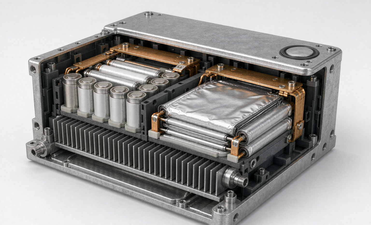
A lithium battery pack is a structural component, not a loose brick of cells. In a battery solution design for equipment, the enclosure must survive the same vibration, shock, and ingress specs as the host device. We typically target IP54 for indoor industrial gear and IP67 for anything exposed. Cell-to-cell spacing, potting compound, and aluminum cooling fins are selected so that a single cell’s fault heat cannot cascade to its neighbors.
Thermal design deserves special attention. Forced-air cooling is cheap but ingests dust; conduction cooling through an extruded aluminum base is cleaner and pairs well with equipment that already has a metal chassis. We model the pack in a finite-element thermal solver before building the first prototype, because discovering a hotspot after tooling is committed is an expensive mistake.
The BMS Is the Real Brain
The cells store energy; the Battery Management System decides whether the equipment survives. A credible custom battery solution uses a BMS with per-cell voltage monitoring, balanced passive or active_top balancing, pack-level current sensing with a fast-acting contactor, and at minimum four independent protection thresholds: over-voltage, under-voltage, over-current, and over-temperature. For connected equipment we add an SMBus or CAN bus so the host controller can read state-of-charge, state-of-health, and fault codes.
I tell clients that a BMS fault log has saved more warranty budgets than any marketing claim. When a pack returns with a swollen cell, the log tells us whether it was over-charged by a faulty charger, deep-discharged by the equipment, or simply old. That data closes the loop on the next battery solution design for equipment.
Safety Certification Floor: UN38.3, IEC 62133, and Beyond
No battery application solutions program leaves our building without clearing the certification floor. For transport, every pack must pass UN38.3 (T.1 altitude simulation, T.2 thermal, T.3 vibration, T.4 shock, T.5 external short, T.6 impact, T.7 overcharge, T.8 forced discharge). For portable equipment cells we design to IEC 62133-2, and for stationary or industrial packs we add IEC 62619 and UL 1973. Systems that feed a building or grid reference UL 9540 and its thermal-runaway propagation test UL 9540A.
Aviation-bound equipment adds a layer of transport compliance under IATA Dangerous Goods with the FAA and EASA recognizing the same UN model; we ship at or below the 30% state-of-charge threshold for air freight unless a full Dangerous Goods approval is in place. None of this is optional. A pack that cannot show its test reports is a liability the moment it crosses a border.
Validation Before Volume Commitment
Before any production run, we validate the battery solution design for equipment through a structured gate: a design review, a functional prototype, a safety test batch, and a field pilot. The pilot is the most revealing. We place 10–20 packs into real equipment at a customer site for 60–90 days and monitor them remotely. If even one pack drifts outside its modeled behavior, we go back to the cell selection or BMS tuning rather than shipping a thousand units that will repeat the anomaly.
This disciplined cadence is why a properly engineered custom battery solution costs more up front than a catalog purchase but costs dramatically less across the product’s life. The math is simple: one field recall on a 5,000-unit equipment line erases any cell-level savings many times over.
FAQ
What is the first step in a battery solution design for equipment?
The first step is capturing the equipment’s real duty cycle — peak and average current, ambient temperature range, required cycle life, and available enclosure volume. Every sound battery solution design for equipment is derived from that load profile rather than from a preferred cell, because the profile determines which chemistry and which thermal strategy will actually survive in the field.
How do I choose between LFP and NMC for my equipment?
Choose LFP when safety margin, long cycle life, and tolerance to daily deep discharge matter most — think industrial robots, medical carts, and stationary systems. Choose NMC when weight and energy density are the binding constraints and you can provide strong thermal management. For cold or cost-sensitive gear, evaluate sodium-ion, and for high-energy portable equipment, consider a semi-solid battery.
Do custom battery solutions require UN38.3 testing for every shipment?
The UN38.3 test report is issued per cell and per pack design, not per shipment, so a validated design carries its approval forward. However, every production lot must remain consistent with the tested configuration, and air shipments still follow IATA Dangerous Goods rules — typically at or below 30% state of charge unless a full approval exists. A reputable battery application solutions partner keeps the test documentation current and auditable.
How long does a battery solution design for equipment typically take?
A straightforward derivative of an existing platform can move from spec to pilot in six to eight weeks. A novel form factor with new chemistry qualification usually runs three to six months including safety certification. Rushing the validation gate is the most common reason equipment programs slip, so we plan the pilot as a fixed, non-negotiable milestone rather than an optional extra.





