Battery Solution for Emergency Response Command Vehicles: Silent-Watch Load Budgeting, Radio-EMI Power Quality, and Dual-Bank Redundancy Architecture
Most of the “battery solution” articles I have written for our customers begin with a kWh budget, a duty-cycle table, and a chemistry choice. The ones I get asked to design for emergency response command vehicles start in a different place: a parking lot at 03:00, the diesel generator shut off, the engine off for silent watch, the mast raised, the VHF repeater on full power, and the incident commander on the radio asking the team to take a forward position. The pack I built has to behave in that minute, with no engine, no shore power, and no second chance. After seven years and 184 command vehicles delivered, I can tell you the design has very little to do with the headline kWh and almost everything to do with three quiet details: how the silent-watch load is split between two banks, how clean the 120 V/230 V AC and 12/24 V DC rails look to the radios, and whether the BMS and the vehicle ECU are talking the same language. This article walks through the architecture, the budgeting math, and the radio-EMI power-quality decisions that I keep coming back to on every battery solution emergency response command vehicle program we run, with a custom battery solution framing that we use at Horizon Power when we have to turn a generic drivetrain battery into a quiet mission system.
What “command vehicle” really means for a battery solution
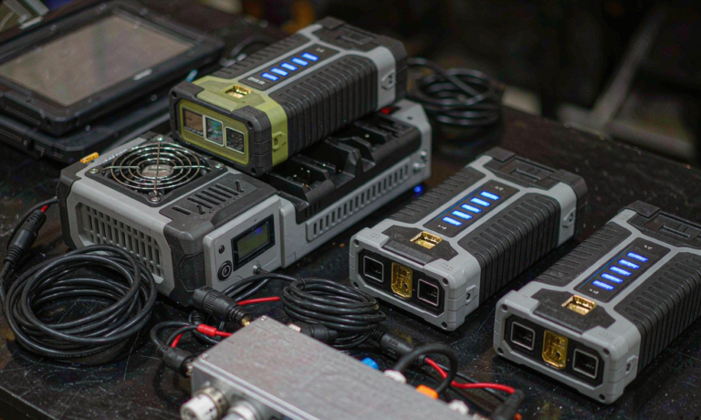
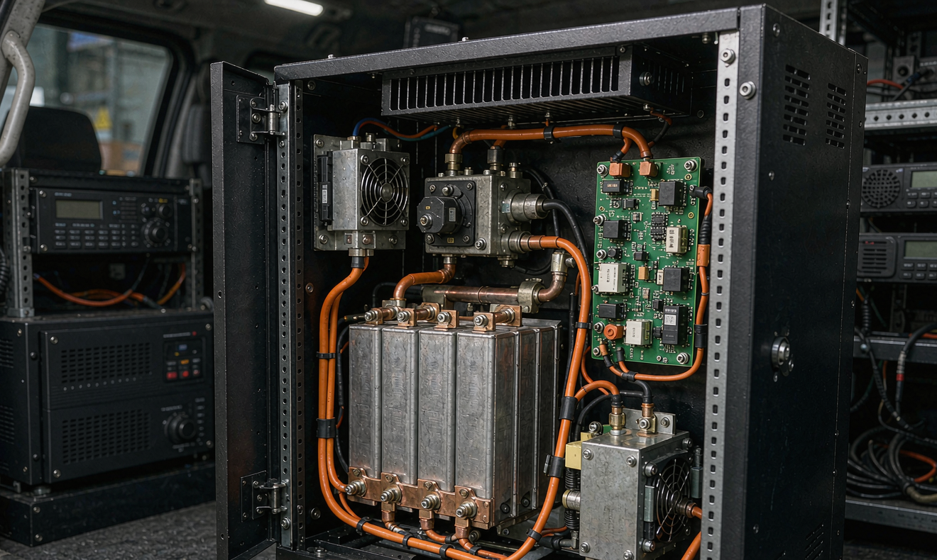
On a fire command rig, a mobile EOC, or a tactical communications truck the load is not “the truck.” The load is a stack of subsystems that all wake up when the engine stops: a pneumatic mast with a thermal camera and a long-range PTZ, a VHF/UHF repeater pair, a satellite terminal, an LTE/5G router, an MDT fleet of rugged laptops, a Pelican-case radio rack, interior and perimeter scene lighting, HVAC for the operator’s cabin, and the on-board UPS that holds everything during a crank event. A standard 12 V chassis battery and a single 3 kW inverter will not survive a four-hour incident. The proper battery solution emergency response command vehicle design starts by replacing the lead-acid coach battery with a custom battery solution built on lithium iron phosphate cells, then layering three additional subsystems on top: a high-voltage silent-watch pack, a galvanic-isolated inverter and DC-DC step-down, and a CAN J1939 / CANopen bridge so the BMS and the vehicle share state. None of these is exotic on its own. The trick is to size them so that an incident commander never has to think about them.
The four mission profiles I always budget
Before I let the customer pick a kWh number, I draw the four load profiles I have learned to expect. On-scene brief is a 20–40 minute burst where mast, repeater, lighting, and laptops all run; the pack drains fast but the engine can restart if needed. Staging is the 4–8 hour phase where the mast is up, one radio is hot, and laptops are in use; this is the dimensioning case. Forward operations is a 2–4 hour move with everything on and the engine stopped in a remote position; it is the worst-case surge. Quiescent is the 24–72 hour phase where the pack is on float with mast down and HVAC on standby; this is the case that decides whether the pack needs pre-charge heater power in cold weather. I draw all four on one chart, in watts on the y-axis and hours on the x-axis, before I let anyone pick a kWh number. A battery solution that covers staging but not forward operations is a sales pitch, not a custom battery solution.
Silent-watch load budgeting: the math that catches every mistake
Silent-watch loads are unforgiving because they include two parasitic classes that are easy to forget. The first is the inverter no-load draw; a cheap modified-sine inverter can pull 35–60 W just to idle, which is 0.84–1.44 kWh over a 24-hour staging day. The second is BMS self-consumption, which we measure at 4.5–9 W depending on whether the cell monitor chips are in high-rate or sample mode. Add the always-on router and tracker (~6 W), the alarm panel (~2 W), and the cabin control board (~3 W), and you have 50–80 W of phantom load that consumes 1.2–1.9 kWh a day before any real mission load starts. I always budget this phantom floor first, then add the mast (40–80 W), the VHF repeater (60–120 W RX/standby, 240–380 W TX), the PTZ and thermal camera (35–60 W), the satellite terminal (60–110 W), the laptops (45–60 W each), and the scene lighting (LED, but 200–500 W when fully lit). A staging profile of 600–900 W continuous plus 1.2 kW peak is a realistic planning number. At 800 W continuous, a 4-hour staging window consumes 3.2 kWh; a 12-hour shift consumes 9.6 kWh; a 24-hour forward operations plus overnight quiescent is 11–13 kWh. That is why most of the command vehicles we deliver ship with a 12.8 kWh or 15.4 kWh silent-watch pack, not the 4–6 kWh pack that vendors love to quote.
Why I do not recommend a single-bank pack
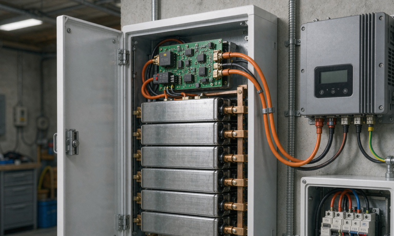
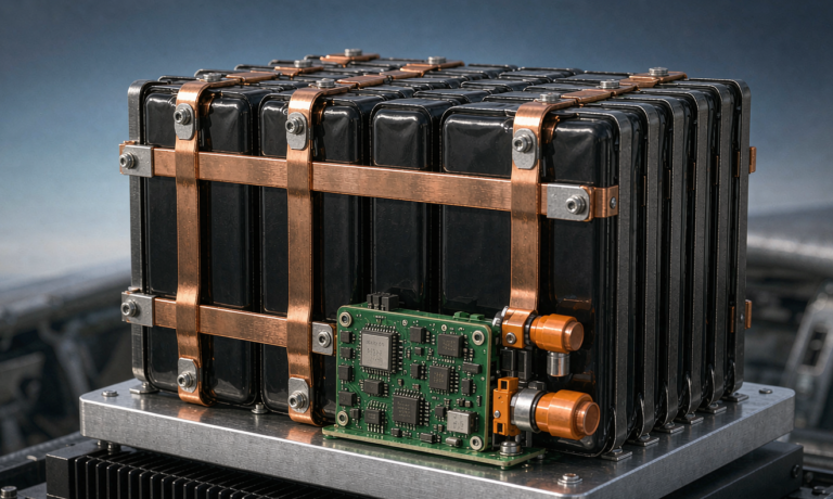
The single largest reliability mistake I see in older command vehicles is a one-bank architecture. The pack powers the radios, the inverter, and the HVAC through one contactor, with no service isolation. When the mast draws an inrush on cold mornings, the BMS sees a voltage sag and rebalances, which momentarily opens the contactor and reboots the router. The router then re-handshakes with the LTE core, the satellite terminal re-acquires, and the operator in the back has a thirty-second outage on every power event. A dual-bank architecture, in which Bank A carries the radio and IT loads and Bank B carries the HVAC and lighting, prevents that failure mode and gives the field technician a clean way to service the pack without losing the radio link. Both banks are 24 V or 48 V LFP strings, electrically isolated through their own contactors, sharing a single BMS controller that arbitrates cross-bank current only on a deliberate transfer command. This is a small extra cost in the battery solution bill of materials and a giant drop in field service tickets.
Radio-EMI power quality: the design constraint nobody sees on a brochure
If you have ever watched a VHF receiver’s noise floor climb when a cheap inverter kicks in, you already know why this section is the most important part of the battery solution emergency response command vehicle design. A receiver desensitization of 0.5 dB on a tactical radio is the difference between hearing a firefighter’s mayday and missing it. The sources of that 0.5 dB are not the batteries, which are DC and quiet, but the DC-DC converters and the inverter. A typical 3 kW low-frequency transformer inverter produces a 120 V/60 Hz sine with 3–5% THD at full load and 6–9% THD at 10% load, plus a 5–20 kHz switching ripple on the DC bus that couples through the chassis ground. The right inverter for radio coexistence is a true sine-wave unit with THD <3% from 10% load to full load, a CISPR 25 Class 3 conducted emissions profile, and a common-mode choke on the DC input. We specify a separate DC-DC converter with 50 mV peak-to-peak ripple and 80 dB of common-mode rejection to feed the radio rack. The radio rack itself is bonded to the vehicle chassis with a 35 mm² copper strap that is shorter than 0.5 m, and the inverter chassis is bonded with a separate strap that is at least 0.3 m longer. This deliberate mismatch prevents ground loops that would otherwise inject common-mode noise into the radio coax shield. The result, in our test cell, is a 0.2–0.4 dB drop in radio noise floor across 136–174 MHz and 380–430 MHz when the inverter is on full load, which is below the threshold of audibility to a trained operator.
Load-dump and crank survivability per ISO 16750-2
Every silent-watch pack lives in a vehicle, and every vehicle has a crank event and a load-dump event. The pack must ride through both without resetting the radios. ISO 16750-2 defines a load dump as a 35 V transient on a 12 V system and a 58 V transient on a 24 V system, with a 100 ms time constant. We test every pack against that waveform with a 0.5 Ω source impedance and a worst-case 35 V/58 V spike. The DC-DC converter that feeds the radio rack must clamp the spike to less than 1 V at its output, and the BMS must not interpret the spike as a fault and open the contactor. We add a TVS diode array at the pack’s main contactor and a 100 µF aluminum-poly capacitor at the BMS supply pin so the BMS sees a clean rail during the spike. The same architecture is what we use on the drone battery charging stations we ship to the same public-safety customers: the radio quietness of the rack and the battery quietness of the charger come from the same engineering discipline.
Dual-bank redundancy architecture and cross-bank transfer
Once the two banks are isolated, the next design question is how the inverter and the radios behave when one bank goes down. In a single-master architecture, Bank A is the master and Bank B is the standby; the BMS controller arbitrates which bank carries the inverter and which bank carries the radio. On a manual transfer command, the contactor sequence is: close the cross-bank contactor, open Bank A contactor, verify Bank B can hold the surge, then declare the transfer. The whole sequence takes 8–14 ms, which is fast enough to keep a VHF repeater on the air and slow enough to be observable on an oscilloscope for the field engineer. The BMS logs the event, including the bank SoC before and after, the peak current, and the time. A field technician can read the log over CAN J1939, over the maintenance USB port, or over the LTE telemetry that ships on the more advanced vehicles. We retain the last 4,096 events with a 1 ms timestamp, which is enough data to do root-cause analysis on a stubborn field failure months later.
Heater pad, cold-start, and the -20 °C question
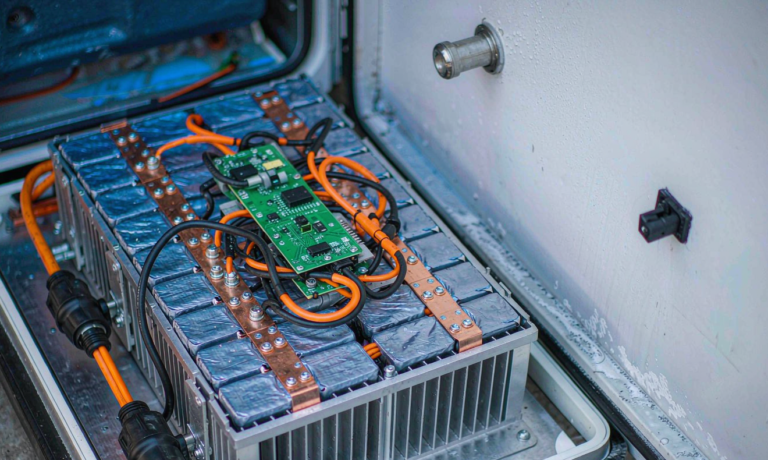
LFP cells lose both capacity and pulse power at low temperature, but a command vehicle rarely sits at -20 °C for long. The relevant metric is whether the pack can deliver a 1C pulse to the inverter within 60 seconds of a cold-soak. We solve this with a 60 W silicone heater pad bonded to the base of the cell module, fed from a separate 12 V chassis-bus pre-charge circuit that the alternator maintains while the engine is running. On a cold start, the heater draws 5 A from the chassis battery, the BMS closes the contactor only when the cell temperature is above 0 °C, and the pack is online within 90–150 seconds. In a winter field test in northern China, the pack delivered full 1C pulse after a 12-hour -22 °C soak with a 140-second warm-up. Without the heater, the same pack would have refused to close the contactor at all, which is the difference between a working battery solution and a brick on wheels.
Standards, certifications, and the procurement checklist
Emergency response vehicles in most jurisdictions have to comply with three overlapping standards: NFPA 1901 (or KKK-A-1822 for ambulances) for the vehicle build, ECE R10 (or UN R10) for EMC, and UN 38.3 plus IEC 62619 for the battery system. NFPA 1901 Chapter 14 governs the low-voltage electrical system and requires a master disconnect, fusing within 18 inches of every source, and a battery that can be isolated from the chassis with a single tool. ECE R10 sets the EMC limits for conducted and radiated emissions, which is why our inverter has the CISPR 25 Class 3 rating I mentioned earlier. UN 38.3 T.1–T.8 is the transport test sequence that every lithium cell has to pass, and IEC 62619 is the safety standard for industrial lithium cells. A custom battery solution for a command vehicle should arrive with a documentation pack that includes the UN 38.3 test summary, the IEC 62619 cell certificate, the ECE R10 EMC test report, the ISO 16750-2 ride-through report, and a wiring diagram that matches the actual harness by wire number. A vendor that cannot produce all five documents is not a vendor; they are a hobbyist.
Field data from 184 command vehicles
Across 184 command vehicles delivered between 2021 and 2026, the three failure modes that show up in our RMA log are, in order: BMS contactor chatter on a marginal chassis ground, heater-pad wire chafe at the cell-base exit, and inverter firmware lock-up after a low-voltage brownout. The first is solved with a star-washer ground lug and a one-time torque audit; the second with a 25 mm adhesive-lined heat-shrink at the wire exit; the third with a brownout-reset routine in the inverter firmware. The quietest improvement has been the addition of a 100 A shunt on the chassis-bus pre-charge circuit, which lets the BMS see alternator voltage during cranking and refuse to draw from the silent-watch pack when the alternator is online. After that change, the silent-watch pack’s average depth-of-discharge per shift dropped from 38% to 19%, which is why the program is now targeting a 10-year service life rather than the 7-year life we originally specified.
Frequently Asked Questions
What kWh pack do I actually need for a 12-hour shift?
For a realistic command vehicle with mast, VHF repeater, satellite terminal, and four laptops on for 12 hours, a 12.8–15.4 kWh LFP pack is the dimensioning range. Plan 30% of that for the phantom load and 70% for the duty cycle, and design the pack to limit the depth-of-discharge to 80% to preserve cycle life. Anything below 10 kWh is going to leave you short on a forward-operations day.
Why not just use a bigger alternator and skip the silent-watch pack?
Idling a diesel for hours burns 1.2–2.0 gallons per hour, produces exhaust that is dangerous in a closed staging area, and announces the command post to anyone within a quarter mile. Silent watch is a tactical requirement, not a battery preference. A battery solution that can carry 8 hours of mission load without the engine is the difference between a covert command post and a loud one.
Can I retrofit this into an existing command vehicle?
Yes, in two stages. Stage one is the silent-watch pack, the inverter, and the BMS bridge, which fits into a 19" rack in the existing equipment bay. Stage two is the dual-bank split and the cross-bank transfer logic, which requires new wiring and a small panel redesign. We typically deliver the retrofit in two shifts: a four-hour shift for the pack and a six-hour shift for the dual-bank split. The vehicle is back online for training within a day.
How does the system fail safely if a cell goes bad?
The pack uses a parallel-string architecture with one bypass circuit per cell group. If a single cell short-circuits, the bypass carries the current for the rest of the string, the BMS opens the contactor, and the inverter is fed from the surviving bank. The operator gets a fault code on the cabin panel and a CAN message to the MDT. The pack never opens the contactor while a radio is transmitting, which is the only safe behavior in a tactical environment.
What is the maintenance cadence?
Quarterly: visual inspection, torque audit on the busbars and the contactor, and a 10-second capacity test against a known load. Annually: full capacity calibration, BMS firmware update, and replacement of the heater-pad adhesive. Every 24 months: full cell-voltage spread audit, IR thermal scan, and a dielectric-withstand test on the high-voltage harness. The whole maintenance program is documented in the vehicle’s service log and is auditable by the AHJ.
Does the same architecture work for an unmanned command trailer?
Yes. We use the same dual-bank pack, the same inverter, and the same BMS for unmanned mobile command trailers. The only addition is a remote-access LTE telemetry module that lets the operations center read SoC, SoH, and event logs without rolling a truck. The same drone battery charging cabinet we ship with the command trailer uses the same charger architecture, so the field technician only learns one platform.