
Battery Solution for Railway and Signaling Systems
When I brief a new railway signaling project as a senior lithium battery engineer, the first question is never “how big a battery do you want” — it is “what happens in the 400 milliseconds after the grid drops.” Railway signaling is a fail-safe discipline. If the trackside power feed fails, the battery must instantly hold the signals in their safe state, keep the interlocking logic alive, and give operations time to react. Over the last decade I have specified backup power for level crossings, interlockings, and trackside telecom nodes across several climate zones, and the pattern is always the same: the battery solution is not an accessory, it is the last line of defense against a wrong-side failure.
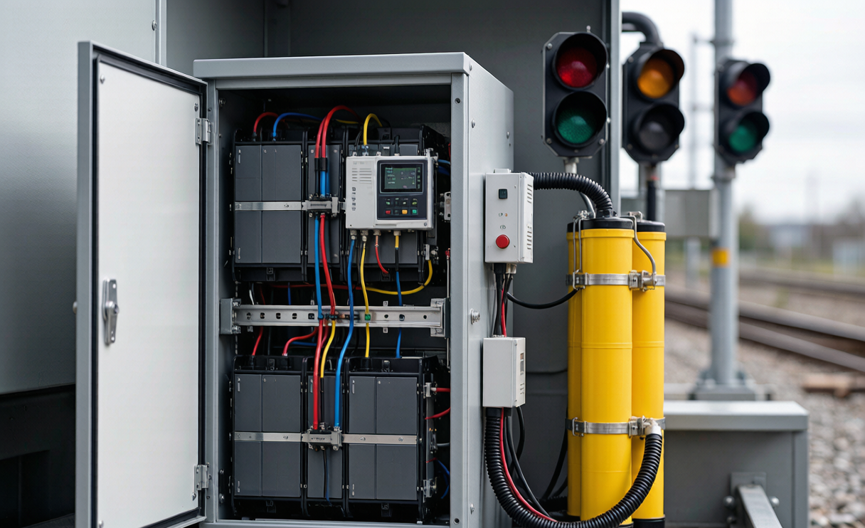
In this field guide I walk through how we engineer a dependable battery solution for railway and signaling systems — the voltage architecture, chemistry choice, sizing math, the battery management layer, and the certification stack that lets a pack survive both a depot and a Himalayan winter. The goal is practical: give you the numbers and the failure modes so you can write a specification that actually holds up.
Why Signaling Systems Cannot Tolerate a Power Gap
A modern signal head, point machine, and axle counter each draw only a few watts, but they must run continuously and, critically, they must fail safe. In a relay-interlocked network the “safe state” is usually the most restrictive aspect — red over green. When mains fails, the battery takes over within a single switching cycle. If the battery cannot deliver, the interlocking may drift to an undefined state, which is exactly what the whole safety case exists to prevent.
This is why signaling backup is designed around hold-up time, not just energy. A crossing may only need two hours of true backup, but it needs that power with near-zero transfer delay and stable voltage. I treat the battery as a continuous-duty float asset that is quietly tested every day, not a once-a-year emergency device.
Voltage Architecture: 24V, 48V and 110V DC in Practice
The dominant trackside bus is 24V DC, inherited from telecom and PLC conventions. Larger interlockings and some European networks standardize on 48V DC, while onboard rolling-stock auxiliaries commonly run at 24V, 60V, or 110V DC. Each step changes the cell count and the fault budget.
- 24V DC: typically 8 cells of LiFePO4 (8S, nominal 25.6V, charge ~29.2V). Simple, cheap, and easy to parallel for capacity.
- 48V DC: 16S configuration (nominal 51.2V). Halves the current for a given wattage, which reduces cable cross-section and I²R losses across long trackside runs.
- 110V DC rolling stock: 36S or 40S stacks with intermediate tap monitoring, common on locomotives and EMUs.
For a custom battery solution on a mixed fleet, I usually standardize the module at 24V or 48V and build the string or parallel bank to the load, rather than designing one odd voltage per site. It keeps spares common and the BMS firmware identical.
Choosing LFP Chemistry for Trackside Safety
For railway signaling I almost always specify lithium iron phosphate (LiFePO4, LFP). The reason is not energy density — it is the safety and abuse tolerance that matters when a cabinet sits unmanned beside a live line. LFP has a stable olivine cathode, operates around 3.2V per cell, and resists thermal runaway far better than NMC. In depot fire-safety reviews that single property removes most of the objections.
A typical LFP signaling cell delivers 2000–4000 cycles at 80% depth of discharge, with a calendar life of 8–10 years under float-like duty. For a standby application that is essentially a decade of service with one capacity verification per year. When a client asks about sodium-ion as a future option, I note its cold-weather edge but remind them that LFP still leads on cycle life and supply maturity for this duty today.
Sizing the Battery: From Hold-Up Time to Worst-Case Load
Sizing is straightforward arithmetic once you respect the duty profile. Start with the worst-case continuous load in amps at the bus voltage, then multiply by the required backup hours, then add the inrush allowance for point machines and crossing gates, which can draw 5–15A for a few seconds.
A concrete example: a level-crossing controller drawing 3A continuous at 24V with a 10A, 3-second gate actuation twice per hour, specified for 4 hours of backup. Energy need ≈ 3A × 4h = 12Ah, plus a modest surge margin, so I specify a 24V 20Ah pack (about 512Wh) to stay above 80% DoD across temperature derating. I always derate capacity by 15–20% for the coldest month, because cell capacity collapses as temperature drops.
This is where a good battery application solution earns its fee: it is not the cells, it is matching the derating curve to the site’s climate data so the pack never silently falls short in January.
The BMS Is the Real Reliability Layer
The cells are commodities; the reliability lives in the battery management system. For signaling I specify a BMS with per-cell voltage monitoring, pack and probe temperature sensing, current measurement with Coulomb counting, and active or passive balancing. It must report state of charge and state of health over the network, because nobody is climbing into a trackside cabinet to read an LED.
Communication is CAN 2.0B or RS485/Modbus to the site controller, with dry-contact alarm outputs for “low battery” and “BMS fault” wired straight into the interlocking’s safe-state logic. A robust BMS solution also includes redundant sensing on the critical cells and a self-test that runs during the daily float charge, so a failed sensor trips before the battery is needed. I have seen more signaling outages caused by a dumb BMS silently losing balance than by cell failure.
Environmental Sealing, Temperature and Cold-Region Design
Trackside cabinets see everything: desert heat, coastal salt, and −30°C winters. I specify a minimum of IP54 for indoor-style enclosures and IP65 for fully outdoor trackside boxes, with conformal-coated PCBs and stainless hardware. Ventilation must be passive or filtered, because fans are a maintenance liability in dusty rail corridors.
For cold regions, LFP loses usable capacity below 0°C and should not be charged below 0°C without heating. On northern lines I add a low-wattage pad heater controlled by the BMS, or specify low-temperature cells rated to −20°C discharge. The trade-off is real: heating draws from the same pack, so I add it back into the sizing math rather than hoping it is free.
Certification Stack: UN38.3, IEC 62133, EN 50155 and Beyond
A railway battery crosses three regimes: transport, cell safety, and rolling-stock immunity. For transport, every pack must clear UN38.3 (the lithium battery test manual covering altitude simulation, thermal, vibration, shock, external short, impact, and overcharge) before it can ride a truck or plane to the depot. At the cell level, IEC 62133 covers portable secondary-cell safety — the baseline I expect from any cell vendor’s dossier.
On the rail side, EN 50155 governs electronic equipment on rolling stock and drives the vibration, shock, and temperature-envelope requirements, while IEC 62619 covers the safety of industrial lithium battery systems and IEC 62485-5 addresses stationary lithium installations. In North America, UL 1973 is the marker buyers recognize. Interestingly, the aviation world leans on FAA and EASA special conditions for lithium installations — when I spec batteries for rail-adjacent airport people-movers, I borrow that same “show me the abuse test” rigor, because the safety philosophy transfers even if the authority does not.
Commissioning and Remote Health Monitoring
A pack is only as good as its first 90 days. I commission with a capacity verification discharge at the site temperature, label the as-found capacity, and set the BMS alarm thresholds against that baseline. From then on, state-of-health is estimated from internal resistance trend and delivered capacity per cycle, pushed to the asset-management dashboard over the existing trackside network.
The payoff is predictability. Instead of “replace every five years,” the operator replaces the specific string that crossed 80% SOH, and the rest keep running. That is the difference between a battery as a consumable and a battery as a managed asset.
Frequently Asked Questions
How long must a railway signaling battery provide backup?
It depends on the asset and the operator’s recovery plan. Level crossings and interlockings commonly target 2–8 hours; remote trackside nodes on long signaling sections may spec 12–24 hours. I always size to the operator’s documented “time to restore mains” plus a safety margin, never to a generic rule.
Can lithium replace VRLA lead-acid in existing cabinets?
Often yes, with caveats. LFP fits the same 24V/48V bus and needs far less maintenance, but you must confirm the charger’s absorption/float profile matches LFP (3.65V/cell max), verify ventilation and fire separation, and replace the dumb lead-acid monitor with a BMS-driven alarm. I have retrofitted dozens of cabinets this way without changing the enclosure.
What standards apply to railway batteries?
At minimum UN38.3 for transport, IEC 62133 for cell safety, IEC 62619 for the system, and EN 50155 for rolling-stock environments, with UL 1973 where North American acceptance is needed. The exact stack depends on whether the pack is trackside, onboard, or both.
How do you monitor battery health remotely?
The BMS reports per-cell voltage, temperature, current, SOC, and SOH over CAN or Modbus to the site controller, which forwards it to the asset dashboard. Alarms for low battery and BMS fault are hard-wired to the safe-state input so a degraded pack never goes unnoticed.
What is the typical lifespan of an LFP signaling battery?
In float/standby duty with proper temperature management, 8–10 years or 2000–4000 cycles at 80% DoD. Real lifespan is governed more by temperature excursions and charge-profile errors than by the cells themselves, which is why commissioning discipline matters.





