
Battery Solution for Unmanned Ground Vehicles (UGVs)
Over the last four years on the engineering floor at Horizon Power, I have watched the unmanned ground vehicle (UGV) market shift from a handful of military prototypes to a mainstream industrial category. Security patrol robots, agricultural weeding bots, warehouse tuggers, and bomb-disposal platforms all share one stubborn truth: their entire mission is gated by the battery solution underneath them. A UGV that loses power mid-mission is not an inconvenience — it is a stranded asset that someone has to walk out and recover. As a senior lithium battery engineer, my job is to make sure that never happens on my watch. In this guide I will walk through how we design a battery solution for unmanned ground vehicles (UGV) that survives shock, dust, temperature swings, and the brutal charge-discharge rhythm of autonomous operation.
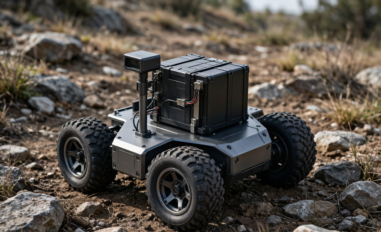
Why UGVs Demand a Purpose-Built Battery Solution
A UGV is not a phone and it is not a laptop. It draws high current during acceleration, crawls at near-zero draw while it processes sensor data, then spikes again when actuators fire. That stop-start profile is hard on cells. When a procurement team comes to us asking for “a battery,” what they actually need is a custom battery solution engineered around their duty cycle, not an off-the-shelf pack borrowed from another industry. I always start by logging real telemetry from their prototype for at least one full week before I commit to a cell type. The peak-to-average ratio tells me more than any spec sheet.
The second reason is packaging. UGVs live in hostile envelopes — heat from motors, vibration from rough terrain, and occasional immersion. A generic battery application solution that works in a climate-controlled cabinet will fail inside a tracked robot. We design the enclosure, the mounting, and the thermal path together with the pack, because in a UGV those elements are inseparable.
Cell Chemistry: LFP vs NMC for Ground Robots
For most UGV programs I recommend lithium iron phosphate (LFP). The thermal runaway window is far wider than nickel-manganese-cobalt (NMC), and for an autonomous machine that may operate unattended, that safety margin is worth more than the extra energy density NMC offers. LFP also tolerates high charge currents, which matters when you want a robot to fast-charge during a brief depot window.
Where NMC still wins is weight-critical platforms — a small throwable recon UGV where every 100 grams changes the mission. In those rare cases I will spec NMC but wrap it in a more aggressive BMS solution with redundant temperature sensing. Chemistry is a trade-off, not a religion, and the right call depends on the platform’s constraints.
Mechanical and Environmental Design
A UGV battery solution has to absorb shock without transferring it to the cells. We use potted cell modules inside an aluminum housing, with silicone dampeners at every mounting point. Ingress protection is typically IP65 for outdoor patrol bots and IP67 for anything that might wade through water. I have seen a competitor’s pack fail a field trial simply because the connector shell cracked after two weeks of vibration — so we specify automotive-grade circular connectors and strain-relieve every lead.
Temperature is the silent killer. A UGV operating in a desert might see 60°C under the hood while the cells themselves stay cooler thanks to a conduction plate. Our battery application solution includes a metal cold-plate bonded to the cell stack and, for cold-climate units, a low-wattage self-heating film that brings cells into their operating window before the motor is enabled. No autonomous system should launch on frozen cells.
BMS Architecture and Communication
The brain of any credible UGV battery solution is the BMS. For ground robots I specify a layered architecture: cell-level protection (over-voltage, under-voltage, over-current, short), pack-level thermal management, and a communication layer that talks to the robot’s main computer over CAN bus or RS485. The robot controller needs state-of-charge, state-of-health, cell temperatures, and fault flags in real time.
A proper BMS solution also enforces graceful shutdown. When a cell drifts, the BMS should warn the UGV to return to base, not silently limp along. I insist on configurable warning and cutoff thresholds per customer, because a 200 kg logistics tugger and a 15 kg inspection bot have completely different risk tolerances. We also log BMS events to non-volatile memory so that, after any failure, the engineering team can replay exactly what happened.
Charging, Hot-Swap, and Autonomy
Autonomy is only as good as the downtime between missions. For depot-based UGVs we design a contactor-controlled charge path that supports 1C to 2C charging with active balancing. For continuous-duty fleets, a hot-swap battery solution lets the robot swap a discharged pack in under a minute and keep working. The mechanical latch, the shielded connector, and the BMS handshake all have to be foolproof, because in a field operation nobody reads the manual.
I also advise clients to size the pack for 20% more than the nominal mission requirement. That headroom covers sensor growth, software updates that draw more compute, and the inevitable battery degradation after 500 cycles. A custom battery solution that is sized perfectly on day one is undersized by year two.
Certifications and Compliance
UGVs that ship internationally must clear UN38.3 for transport, and we design packs to pass IEC 62133 for cell safety. If the robot carries payloads on commercial aircraft or operates near the public, we also align with regional EMC and electrical safety marks. From the first prototype I keep a traceable dossier — cell batch records, formation data, and test logs — because a credible battery solution provider can produce that paperwork on demand, not three months later.
How We Engineer Your UGV Battery From Brief to Certified Product
When a client engages Horizon Power, we begin with a duty-cycle capture, move to cell selection and a 3D-pack concept, then build and abuse-test prototypes before pilot production. This structured path is what separates a reliable battery application solution from a box of cells with a strap. For UGV programs the loop usually runs six to ten weeks from brief to first certified pilot units, and we stay involved through the field trial because that is where the real design lessons show up.
Sizing the Pack: A Worked Example
To make the math concrete, consider a 120 kg logistics UGV that draws 600 W average and peaks at 2.4 kW during incline climbs. At a nominal pack voltage of 48 V, the average current is 12.5 A and the peak is 50 A — a 4C peak that an LFP pack rated for 15C discharge handles comfortably. For a 6-hour shift at average load, the energy need is 3.6 kWh. Applying my 20% headroom rule, I would specify a 4.3 kWh pack, which at 48 V is roughly 90 Ah. Round-cell 21700 LFP cells at about 5 Ah each mean we parallel 18 strings; with cell-level fusing that is a robust, serviceable layout. I always verify the result against logged telemetry rather than trusting the estimate, because real-world rolling resistance and sensor load routinely add 15–25% to the textbook number.
The same worked example drives connector and cable selection. A 50 A peak at 48 V demands 6 mm² silicone cable with derating for the duty cycle, and a contactor rated for inrush current. These are the unglamorous details that decide whether a battery solution survives its first month in the field, and they are exactly where a cheap generic pack falls apart.
Field Maintenance and End-of-Life Planning
A UGV battery solution is a long-lived asset, and I design for the whole lifecycle rather than just the launch. We program the BMS to record cumulative throughput so state-of-health can be reported to the fleet manager, triggering pack retirement before capacity falls below 80% of nameplate. For end-of-life, LFP is far easier to recycle than cobalt-heavy chemistries, and we provide a take-back pathway so clients meet their own sustainability commitments without scrambling at disposal time. Planning the exit at the design stage is part of what I consider a complete battery application solution, and it is the difference between a pack that is merely compliant and one that is genuinely low-risk to operate for years.
Frequently Asked Questions
What battery chemistry is best for an outdoor UGV?
For most outdoor and unattended UGVs I recommend LFP for its wide thermal safety margin and high charge tolerance. NMC is reserved for weight-critical micro-platforms where the energy-density gain outweighs the added BMS complexity.
How do you protect the battery from vibration and shock?
We pot the cell modules, mount them on silicone dampeners inside an aluminum housing, and use automotive-grade connectors with strain relief. The goal is to keep shock from reaching the cells and to keep the enclosure from cracking over thousands of vibration cycles.
Can a UGV battery be hot-swapped in the field?
Yes. For continuous-duty fleets we design a hot-swap battery solution with a mechanical latch, shielded connector, and BMS handshake so the robot can swap a pack in under a minute without the operator reading a manual.
How does the BMS communicate with the robot?
Typically over CAN bus or RS485, reporting state-of-charge, state-of-health, cell temperatures, and fault flags in real time so the robot controller can plan returns-to-base before the pack is critical.
Which certifications does a UGV battery need?
At minimum UN38.3 for transport and IEC 62133 for cell safety, plus regional EMC and electrical safety marks if the robot operates near the public or ships commercially. We maintain a traceable dossier from the first prototype.
How much extra capacity should I spec beyond the mission requirement?
I advise 20% headroom above nominal mission load. That covers sensor and compute growth over the product’s life and the natural degradation after a few hundred cycles, keeping the battery solution useful well into year two.





