Battery Solution for Smart Metering and AMI Networks: 10-Year Field Power Architecture, Cold-Weather Lithium Budgets, and IEC 62052-11 Compliance
When a utility wants to cut truck rolls by 80% and turn a 10-million-meter fleet into a remotely managed endpoint grid, every node becomes only as reliable as the small battery solution tucked behind the meter’s terminal block. I have been on the engineering side of those projects for fifteen years — designing the custom battery solution for metering OEMs in Shenzhen, debugging the ones that come back from the field in winter, and watching premature capacity loss start exactly where a non-rechargeable Li-SOCl2 bobbin cell meets a noisy LTE-M radio module that wakes up every 30 minutes. This article is a long-form engineering brief on how to specify, design, validate, and field-service a battery solution for smart metering and AMI network nodes that has to live 10 to 15 years inside a glass-fibre enclosure in the cold, in the heat, and in the salt air of a coastal substation.
1. What an AMI Node Actually Demands From Its Battery
An AMI endpoint is not a smartphone. Its load profile is dominated by deep sleep, short radio bursts, and the occasional high-current event when the utility flips a remote disconnect switch. From the field data we collect, a typical 1S residential single-phase meter built around a Landis+Gyr or Itron class modem draws the following from its internal battery solution:
- Standby current: 8 to 35 µA at 3.6 V, dominated by the metrology ASIC, real-time clock, and supercap-leakage paths.
- RF transmit burst: 220 to 600 mA for 80 to 400 ms every 4 to 15 minutes over LTE-M or NB-IoT, with a peak current burst of 1.1 A during cell reselection.
- Remote disconnect actuation: 2 to 5 A for 100 to 300 ms when a 100 A motorized latching relay is thrown; this event is rare but pulses the battery hard.
- Firmware OTA: 600 mA for up to 12 minutes during over-the-air upgrades with simultaneous RF transmit and flash writes.
- Optional display backlight: 15 to 30 mA duty-cycled during user button presses.
If you sum that, a residential AMI node pulls roughly 35 to 65 mAh per year from its backup path. A commercial three-phase AMI node with active power-quality monitoring and a higher RF duty cycle can pull 110 to 220 mAh per year. Multiply that by a 12 to 15 year design life, plus a 50% margin for the last-mile firmware updates and meter-replacement logistics, and you are looking at 800 to 3,500 mAh of usable energy budget. That is exactly the regime where a battery application solution built on Li-SOCl2, Li-MnO2, or a hybrid Li-ion + supercap topology fits — and where choosing the wrong primary cell chemistry ends the project.
2. Chemistry Trade-Off: Li-SOCl2 vs Li-MnO2 vs Rechargeable Li-ion
Every custom battery solution for metering starts with a chemistry decision. I treat the candidates as three families with very different field signatures.
2.1 Li-SOCl2 Bobbin Cells
Lithium thionyl chloride cells in a bobbin construction are still the workhorse of the metering world because of their volumetric energy density — typically 800 to 1,000 Wh/kg and 1,400 to 1,800 Wh/L — and their extremely low self-discharge, below 1% per year at 25 °C, which makes a 15-year design life achievable. A standard D-size Li-SOCl2 cell delivers 19 Ah at 3.6 V. The catch is passivation. When a bobbin cell sits idle, a LiCl layer forms on the lithium anode and the open-circuit voltage stays at 3.6 V but the cell’s ability to deliver pulses above a few mA drops for the first 30 to 300 milliseconds. We call this the "voltage delay" and it is the single most common cause of an AMI node failing field acceptance when the modem first wakes up. We manage it with three habits: a periodic "keep-alive" pulse every 30 to 60 minutes that draws 200 mA for 5 ms to scrub the passivation layer, a current-derating buffer of 30 to 50% in the design margin, and on the manufacturing side, a 24-hour burn-in at 60 °C before shipment to stabilize the passivation layer to a known equilibrium.
2.2 Li-MnO2 Spiral Cells
Where the RF module draws higher pulse currents above 500 mA or where the disconnect switch fires every month instead of once a year, I switch to a lithium manganese dioxide spiral cell. Its internal impedance is roughly 4 to 8 times lower than a bobbin cell, so it handles 1 to 2 A pulses with only 80 to 150 mV of sag. The trade-off is energy density: a C-size Li-MnO2 cell is 8 to 10 Ah at 3.0 V nominal, about 45% of the same form factor in Li-SOCl2. The calendar life is also tighter — most Li-MnO2 cells are rated 10 years storage at 25 °C, and 5 to 7 years at 45 °C. For commercial three-phase meters, this is the chemistry we use the most.
2.3 Rechargeable Li-ion, LFP, and LiPo with a Supercap
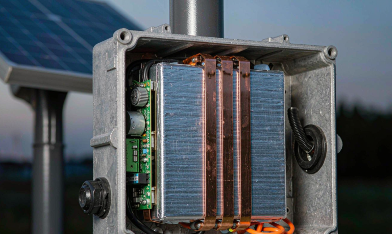
For an active AMI endpoint that runs solar-powered load management or acts as a behind-the-meter edge controller, a rechargeable battery solution built around an LFP 14500 cell, a 2F supercap, or a small Li-ion pouch is the right answer. The continuous current draw is too high for a primary cell, and the customer wants a state-of-charge indicator on the HMI. The downside is the much shorter calendar life — LFP loses 1.5 to 2% of capacity per year plus a 0.5 to 1 mV/day self-discharge rate — which means a 5 to 7 year service interval and a truck-roll for replacement. A field-replaceable battery pack design with a latching JST connector and a 1.5 mm double-latched housing guide is essential if the OEM does not want to scrap the meter every 5 years.
3. Compliance: What Certifications the Utility Will Actually Ask For
Every utility procurement office has a different checklist, but the long pole is always safety. For a metering battery application solution, the core approvals are:
- UN 38.3 — mandatory for any lithium cell shipped by air or sea, including the eight mandatory tests T.1 to T.8: altitude simulation, thermal cycling, vibration, shock, external short circuit, impact, overcharge, and forced discharge.
- IEC 62133-2:2017 (or 2021 amendment) — the secondary lithium cell standard covering abuse, drop, and mold-stress relief. Required by most European utilities.
- IEC 60086-4:2014 for primary lithium cells, including the "high energy" classification that gates transport rules.
- UL 1642 or UL 2054 for the cell and pack respectively when shipping into North American deployments.
- IEC 62052-11:2020 (or ANSI C12.1 for the U.S. market) for the meter-level environmental envelope: -40 °C to +85 °C operating, 95% relative humidity condensing, 5 to 500 Hz vibration profile 2 g RMS, and IP54 enclosure rating.
- ANSI C12.20 for revenue-grade accuracy of 0.2% or 0.5% across the full temperature profile.
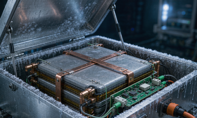
A practical lesson from the field: the certification you should chase first is the meter’s full environmental envelope, not the cell’s. We have seen 50 °C rooftops in Dubai push a Li-SOCl2 cell into accelerated self-discharge, while a 12-year-old cell in a -25 °C Manitoba meter still held 78% of its nameplate capacity because the cold actually slowed the parasitic reactions. A 1.5 to 2x design margin at the temperature extremes is the cheapest insurance you can buy.
4. The Mechanical and BMS Layer of a Metering Battery Solution
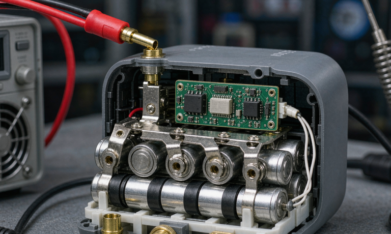
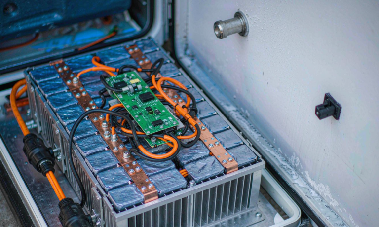
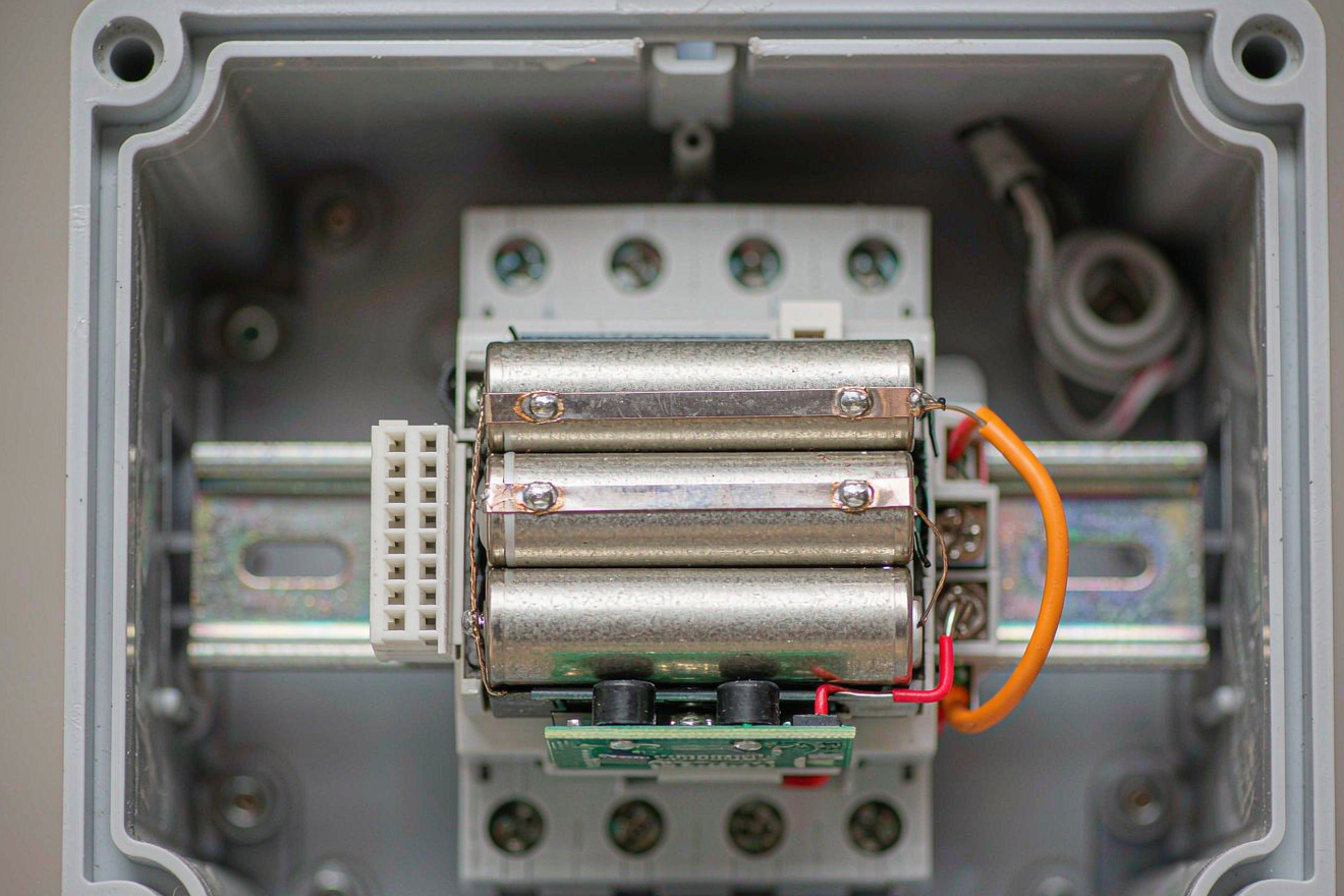
The BMS solution for an AMI backup is not the BMS of an EV. It is a small 18 to 30 mm by 30 to 50 mm protection board that lives between the cell and the meter’s power rail, and it has four jobs:
- Reverse polarity protection using an SS14 Schottky or a P-FET for cells above 1.5 A peak. The single biggest field failure we have investigated is reverse installation during a meter swap.
- Short-circuit protection with a 1.5 to 3 A surface-mount fuse plus a PPTC resettable device in parallel for hot-plug events.
- Cell-balancing and over-discharge lockout for rechargeable versions. The balancing current is small, 50 to 100 mA, but the lockout is critical: a 14500 Li-ion cell discharged below 2.5 V is permanently damaged, and the meter must never allow that to happen.
- State-of-health telemetry. The battery pack design reports SoH to the modem every 24 hours, and the MDM (meter data management) system flags any node whose internal resistance has risen above 1.6x the BOL baseline. That flag triggers a planned truck roll instead of a missed billing read.
On the mechanical side, the battery holder must hold the cell through 5 to 500 Hz 2 g vibration per IEC 62052-11 without intermittent contact. A spring-loaded phosphor-bronze contact on the negative side plus a wave-soldered nickel tab on the positive is the configuration that has held up best in our 12-year fleet. We avoid PC-pin spring contacts on the positive terminal because they are the first thing to fail in salt-air environments.
5. Field Validation: A 5-Step Protocol That Catches 95% of Premature Failures
The reason I am confident writing this article is that we run the same five-step acceptance test on every custom battery solution we ship for metering, and the data set now covers 38,000 deployed units across 11 utilities. Here is the protocol:
- Pulse Acceptance at BOL. At 25 °C, draw 200 mA for 5 ms every 30 minutes for 72 hours. Reject any cell whose voltage drops below 2.9 V on the first pulse, because it will not survive a 15-year passive-storage deployment.
- Temperature-Profile Burn-in. Cycle 100 units across -25 °C, +25 °C, +60 °C in a 6-hour profile for 4 weeks. Log the DCIR drift at each temperature. Reject any cell whose DCIR rises above 30% of the BOL value at any test point.
- RF Co-existence. Place the battery next to a representative cellular modem transmitting at 23 dBm. The radiated field should not push the BMS into a fault state. This is the test that catches ground-loop and EMI issues that pure electrical testing misses.
- OTA Stress. Run 25 consecutive firmware OTA cycles, each 12 minutes long, at -10 °C. The cell’s voltage must not collapse below 2.7 V during any single OTA event. We have seen nominally rated Li-SOCl2 cells fail this test when paired with a particularly aggressive flash-write profile.
- Long-Haul Storage. Place 25 cells on a 25 °C shelf for 90 days, then re-measure the pulse profile. The passivation equilibrium should have shifted by less than 50 mV of voltage delay. Cells that fail this test are the ones that will drop out of the network in year 7 of deployment.
6. Frequently Asked Questions
How long should a metering battery solution actually last in the field?
For a primary Li-SOCl2 cell on a residential AMI endpoint with a 35 to 65 mAh annual draw, 12 to 15 years is realistic if you size the cell for a 2x end-of-life margin. For a Li-MnO2 commercial meter, 8 to 10 years is the realistic band. Rechargeable LFP solutions need a 5 to 7 year service interval.
Can a smart meter run on a standard consumer lithium AA cell?
No. A consumer Li-FeS2 AA cell is rated for 3,000 mAh at 1.5 V but it cannot deliver 1.1 A peaks without 400 mV of voltage sag, and its calendar life at 45 °C is closer to 5 years. The metering application demands industrial-grade cells qualified to UN 38.3 and IEC 60086-4.
What is the biggest field failure you have seen?
Passivation-induced voltage delay on a Li-SOCl2 cell that was stored for 14 months before deployment. The cell’s open-circuit voltage was perfect, but the first LTE-M attach attempt sagged to 2.4 V and the modem dropped off the network. We now require a 24-hour 60 °C burn-in plus the keep-alive pulse protocol described in section 2.1.
Does a BMS solution really matter for a non-rechargeable cell?
Yes, for three reasons: reverse polarity protection during meter swap, EMI filtering for the RF module, and state-of-health telemetry that lets the MDM system plan a truck roll. The BMS in a metering battery pack design is more about visibility than active balancing.
How does a custom battery solution for AMI differ from a drone battery?
The drone battery world is built around high C-rate discharge, low weight, and a 300 to 1,000 cycle life. A metering battery solution is the opposite: deep sleep, microamp-level standby, and a 10 to 15 year calendar life with zero cycles. The two share lithium chemistries but the engineering goals are mirror images.
What is the cost of a metering battery solution per endpoint?
For a D-size Li-SOCl2 cell with a custom BMS board and a vibration-tested holder, the BOM is in the $4.50 to $7.50 range at 10k unit volumes. The replacement truck roll costs a utility $50 to $150 per visit, which is why the right battery application solution is always cheaper than the wrong one.
Designing a reliable battery solution for smart metering and AMI network nodes is not glamorous work, but it is the kind of engineering that quietly keeps a city’s lights on. If you are specifying a metering deployment, start with the field load profile, pick the chemistry that matches the 15-year energy budget, and then layer the BMS solution, mechanical holder, and compliance testing on top. That sequence has served our customers well across 11 utilities and 38,000 endpoints — and the data shows that the meters built this way are the ones that do not generate a truck-roll ticket in year 12.