Battery Solution for Water and Wastewater Monitoring
I have spent more than a decade specifying industrial battery packs for remote and unmanned sites, and water infrastructure keeps teaching me the same lesson: the hardest part of a monitoring battery is not the battery itself. It is the load profile you never measured, the condensation you did not plan for, and the cold morning when the BMS refuses to charge because the chamber dropped below freezing. A battery solution for water and wastewater monitoring has to survive wet wells, hydrogen sulfide, flood immersion, and years of hands-off operation, all while powering telemetry that must not miss a data point. In this guide I will walk through how we size, select, protect, and commission battery systems for level sensors, flow meters, samplers, and pump-station telemetry, using the same duty-cycle math and acceptance checks I apply on real projects.
Why Monitoring Nodes Are a Different Battery Problem
Water and wastewater monitoring sites are not miniature UPS systems. A plant room backup battery sees a large, known load for a defined ride-through window. A monitoring node sees a handful of watts running for weeks without attention, a transmit burst that spikes tenfold, and an environment that actively attacks every metal part in the enclosure.
Typical measured loads I work with:
- RTU or data logger: 1 to 5 W continuous, depending on logging rate and local display.
- Cellular modem: 0.5 to 3 W idle, 8 to 15 W during transmission bursts that last 2 to 20 seconds. NB-IoT nodes average far lower than LTE nodes, often under 1.5 W for the whole radio budget.
- Ultrasonic or radar level sensor: 0.3 to 1 W average, with transmit peaks of 5 to 15 W.
- Automatic sampler: peristaltic pump 20 to 60 W per sample cycle, and a refrigerated sampler base unit adds 50 to 150 W continuously, which changes the entire power budget.
- Valve or gate actuators: 30 to 100 W bursts of a few seconds, a few times a day at most.
- Storm-event CCTV: 10 to 25 W with IR illuminators, usually event-triggered rather than continuous.
The failure mode I see most often is not battery capacity but peak current. A modem drawing 2 A at 12 V for twenty seconds will drag the bus down if the pack or the cabling cannot supply it, the RTU brownouts, the last log file corrupts, and the client blames the battery. Peak-to-average ratios of 5:1 to 10:1 are normal at these nodes, so the battery and its BMS must be rated for the burst, not just the average.
Sizing: Do the Duty-Cycle Math Before Choosing Anything
I size every node from a 24-hour energy table, not from the vendor datasheet. The arithmetic is simple, but skipping it is the single most common cause of dead sites.
Example: a manhole flow-monitoring node with an area-velocity sensor, an LTE modem reporting every 15 minutes, and no local display.
- Average load: logger 2 W + modem average 2.5 W + sensor average 0.5 W = 5 W
- Daily energy: 5 W x 24 h = 120 Wh/day
- Required autonomy without sun or mains: 14 days = 1,680 Wh of usable energy
- Corrected for 90% depth of discharge, 92% conversion efficiency, and 80% end-of-life capacity: 1,680 / (0.90 x 0.92 x 0.80) = 2,536 Wh nominal
- Select a standard 2.5 to 2.6 kWh LFP pack, for example 25.6 V x 100 Ah.
For a refrigerated sampler on mains with battery backup, the numbers change completely: 100 W base load x 8 h ride-through = 800 Wh usable, which after the same derating needs roughly 1.2 kWh. But the battery must also deliver the sampler’s 5 to 8 A starting current at end of discharge, which is a BMS current-limit question, not a capacity question.
Three sizing rules I apply without exception:
- Compute autonomy first, recharging second. A solar array sized for the average annual sun will still leave the node dark during three weeks of winter storms at 45 degrees latitude.
- Derate to end of life. Specify for 80% capacity, not the nameplate value. The pack ages from the first cycle.
- Check the burst. Confirm the pack’s continuous and pulse current ratings at the coldest expected temperature, because available current falls sharply below 0 degrees C.
Chemistry Selection: LFP, NMC, Sodium-Ion, and Primary Lithium
There is no single best chemistry for a battery solution in this sector; the right choice depends on autonomy length, climate, and service model.
- LiFePO4 (LFP) is my default for rechargeable nodes. 150 to 180 Wh/kg, 4,000 to 6,000 cycles at 25 degrees C, and an ARC self-heating onset near 250 degrees C makes it forgiving in unmanned cabinets. Its flat voltage curve means the BMS needs coulomb counting for accurate state of charge, and it must never be charged below 0 degrees C without a heater.
- NMC 811 earns its place where the enclosure is volume-limited, such as inside compact manhole mounts: 240 to 280 Wh/kg cuts pack mass by roughly a third. The trade-offs are a shorter cycle life of 2,000 to 3,000 cycles, an ARC onset of 110 to 140 degrees C, and stricter thermal design. I require a 45 degrees C charge cut-off and robust cell-level fusing when I approve NMC for underground or confined installations.
- Sodium-ion is compelling for cold climates. Retaining 85 to 92% of capacity at -20 degrees C where LFP delivers 70 to 80%, and tolerating low-temperature charging far better, it suits unheated cabinets in northern sites. Expect 25 to 40% more cabinet volume for the same energy, and confirm the modem’s voltage window, because a sodium pack sweeps 1.5 to 4.0 V per cell compared with LFP’s 2.5 to 3.65 V.
- Primary lithium-thionyl chloride remains the champion for genuinely service-free 5 to 10 year nodes: 500 to 700 Wh/kg, excellent shelf life, and passivation behavior that suits tiny average loads. It is non-rechargeable, expensive per Wh, and restricted in transport, so I reserve it for sub-50 W average loads where a site visit costs more than the cells.
When a client asks for a single chemistry across a mixed fleet, I push back politely. A custom battery solution that pairs LFP at pump stations with primary lithium on low-rate river gauges often halves the ten-year cost compared with forcing one product everywhere.
Surviving Water, Humidity, and Hydrogen Sulfide
Wastewater atmospheres are among the most corrosive environments an electronics enclosure will ever face. Hydrogen sulfide oxidizes to sulfuric acid on copper surfaces, and I have seen unprotected copper busbars grow black sulfate films within months in a wet well headspace. The design measures that matter:
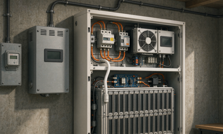
- Enclosure rating: IP66 as the baseline for outdoor cabinets, IP68 where splash or brief immersion is plausible. Verify with an actual hose test at commissioning, not just the datasheet.
- Conformal coating on all PCBAs to IPC-CC-830, including the BMS. Uncoated BMS boards are the most frequent early failure I find at humid sites.
- Plated hardware: nickel-plated copper busbars and tin-plated terminals; 316 stainless fasteners anywhere near the basin. Bare aluminum and copper do not last in H2S environments.
- ePTFE breather vents to equalize pressure and purge condensation. A fully sealed cabinet without a vent breathes humid air in and out through the door gasket as the temperature swings 25 K per day, and will accumulate tens of milliliters of condensate within a year.
- Mount above flood level: I specify cabinet bases at least 450 mm above the 100-year flood line or the wet well rim, and I ask for photos of the mark on the wall when I cannot visit.
For nodes installed inside manholes or digester areas, ventilation classification comes first. Battery electronics in a classified Zone 1 or Zone 2 atmosphere need intrinsically safe or Ex-rated enclosures per IEC 60079 series, and that decision must happen at design stage, because retrofitting Ex compliance onto a standard pack is not realistic.
Temperature Extremes and the Zero-Degree Charging Rule
Monitoring nodes see the full annual temperature swing because nobody heats an unmanned cabinet. Buried chambers are gentle, typically 5 to 25 degrees C year round. Pole-mounted cabinets on a sunny embankment can reach 55 to 65 degrees C internally in summer and -25 degrees C in a continental winter.
Heat and cold both cost capacity, in opposite ways. At 45 degrees C, LFP cycle life falls from 4,000-6,000 cycles to under 2,000; calendar aging roughly doubles every 10 degrees C. Below freezing, charge acceptance collapses, and charging an LFP cell below 0 degrees C plates lithium metal onto the anode, a permanent and cumulative capacity and safety loss.
The design response is straightforward and non-negotiable:
- BMS with a hard charge inhibit below 0 degrees C and a resistive or PTC heater pad (5 to 8% of daily energy in the coldest months) that raises cell temperature above 5 degrees C before allowing charge current.
- Discharge allowed down to -20 degrees C with derated current; below that, expect 70 to 80% capacity from LFP and plan autonomy accordingly.
- Shade, light-colored cabinet finish, and separation from sun-facing walls to keep summer internal temperatures within 10 to 15 degrees of ambient.
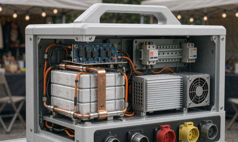
- Active cooling only when annual average load exceeds roughly 100 W continuous; below that, a well-vented IP66 cabinet with a breather valve does the job with zero parasitic drain.
Recharge Versus Replace: Solar, Mains, and Hybrid Power Architecture
Every node falls into one of three power architectures, and mixing them up is expensive.
Solar-autonomous nodes (river gauges, canal levels, remote outfalls) need the array sized for the worst month, not the average. A 120 W panel in central Europe yields 170 to 260 Wh/day in December at 2 to 3 peak sun hours with 0.75 system derate; against a 120 Wh/day node that is a thin margin once snow, shading, and soiling are counted. I specify 200 to 300 W of panel per 120 Wh/day of load in latitudes above 40 degrees, an MPPT controller with temperature-compensated LFP charging, and at least 7 days of full autonomy in the pack.
Mains-backed nodes (pump stations, plant telemetry, sampler stations) use a small AC-DC charger sized at 0.15 to 0.3 C so a depleted pack recovers overnight. Float charging LFP at 100% state of charge year after year accelerates calendar aging; I set standby at 30 to 60% SOC with a scheduled monthly top-up, and I make sure the BMS supports it. VRLA batteries wanted a permanent float; lithium wants a rest.
Hybrid sites (satellite backhaul, high-rate samplers) pair solar with a DC genset input or a swap-out program. If the node uses satellite telemetry, budget 5 to 20 W for the modem and expect the transmit budget to dominate; store-and-forward logging with one batch transmission per hour can cut radio energy by 60 to 80% compared with per-sample uploads.
Where a client’s fleet spans all three, I standardize the battery interface: same connector, same mounting footprint, same BMS protocol, so a technician carries one spare and one cable kit. That standardization is usually worth more than another 10% of Wh per dollar.
Safety and Compliance Checklist
Compliance for a monitoring battery solution is narrower than for EV or storage but not optional, and the transport rules catch teams off guard every year.
- Cell safety: IEC 62133-2 for portable-class cells or IEC 62619 for industrial stationary use; UN 38.3 test summary for every pack shipped (transport at or below 30% state of charge for lithium chemistries).
- System level: UL 1973 or UL 9540 where the AHJ requires it, particularly in North American pump-station retrofits.
- Ingress protection: IEC 60529 IP ratings verified by test, plus IEC 60068-2-30 damp heat cycling for humid-climate proof.
- Hazardous areas: IEC 60079 / ATEX / IECEx certification for batteries installed in classified zones around digesters, headspaces, and biogas piping; NFPA 820 guides ventilation classification at wastewater plants in the US.
- EMC: IEC 61000-6-2 immunity and IEC 61000-6-3 or 6-4 emissions, since the modem bursts sit millimeters from the BMS sensing lines.
One documentation item saves months: keep the UN 38.3 test summary, SDS, and label artwork in the same folder as the installation manual. The most common shipping failure I see is a node whose label Wh rating does not match the pack datasheet after a mid-life cell change.
Commissioning and Acceptance: What I Verify Before Signing Off
A battery that has never been tested under load is a rumor. My commissioning sequence takes half a day per node and has caught every early-life failure mode I have ever traced:
- Insulation resistance: 500 V megger between bus and chassis above 100 megohms; below 10 megohms, do not energize, and look first for a failed breather valve and condensation.
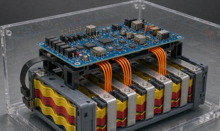
- Cell balance: after a full charge and a 2-hour rest, cell voltage spread under 30 mV. Spread that only appears under load points to connection resistance, not cells; retorque and re-measure.
- Capacity check: a 0.2 C discharge delivering at least 95% of rated Ah at 25 degrees C.
- Burst test: trigger the modem’s worst-case transmit with the pack at 20% SOC and confirm the bus stays within the RTU’s brownout window.
- Cold-charge interlock: bench-verify the BMS refuses charge below 0 degrees C and releases it above 5 degrees C after heater operation.
- Thermal scan: 30 minutes at full load, then an IR camera over busbars and terminals; any joint more than 15 K above its neighbor gets re-torqued.
Finally, I log the baseline: measured capacity, 1 kHz impedance per cell group, rest voltage spread, and firmware versions. Trending impedance upward by 25 to 30% predicts the end of a pack’s service life 300 to 500 cycles before the capacity curve admits it, which is exactly the notice period a water utility needs to schedule a swap.
Frequently Asked Questions
How long should a battery solution for a remote water monitoring node last?
A well-specified LFP pack at 25 degrees C delivers 4,000 to 6,000 cycles and 10 or more years of calendar life at partial state of charge. In hot or deeply cycled applications, plan for 5 to 7 years, and size the enclosure so the swap takes under 30 minutes.
What size battery does a typical wastewater level sensor need?
A 5 W average-load node reporting over LTE every 15 minutes consumes about 120 Wh per day. Fourteen days of autonomy requires roughly 2.5 kWh nominal after derating for depth of discharge, efficiency, and end-of-life capacity. Shorter autonomy windows scale down from there.
Can lithium batteries be installed inside manholes and wet wells?
Only outside classified atmospheres, or inside Ex-certified equipment where the zone classification demands it. Wet well headspaces and digester areas are frequently Zone 1 or Zone 2 per IEC 60079 and NFPA 820, so the battery enclosure must match the hazardous-area rating before installation is legal.
Why does my solar-powered monitoring node keep dying in winter?
Almost always a sizing error: the array was dimensioned for average annual insolation rather than the worst month, or the battery was allowed to charge below 0 degrees C and lost capacity to lithium plating. Size panels for the darkest month and require a heated, temperature-gated charge path.
Is LFP still the best chemistry for outdoor telemetry cabinets?
For most sites yes: it offers the best cycle life, the highest thermal-runaway onset temperature, and tolerant behavior in unmanned service. NMC suits volume-limited mounts, sodium-ion suits cold climates, and primary lithium suits 5 to 10 year no-service nodes, but LFP remains the default industrial battery for general telemetry.
How do I protect the battery from hydrogen sulfide corrosion?
Use IP66 or better enclosures with ePTFE breather vents, conformal-coat every board to IPC-CC-830, specify nickel-plated copper busbars and 316 stainless fasteners, and mount the cabinet above flood level with the door shielded from direct splash. Never leave bare copper or aluminum exposed in wet well atmospheres.
Do I need UN 38.3 certification to ship a replacement monitoring battery?
Yes. Any lithium cell above 20 Wh or battery above 100 Wh ships as Class 9 dangerous goods and requires the UN 38.3 test summary, correct packaging instructions (PI 965 to 967 for air freight), and lithium at or below 30% state of charge. Sodium-ion packs fall under UN 3551 and UN 3552 with their own documentation.
What maintenance does a monitoring battery solution actually require?
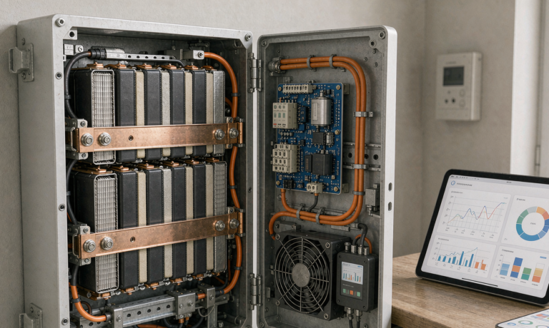
Very little if the baseline is set correctly: quarterly review of BMS telemetry (cell spread, impedance trend, temperature hours above 35 degrees C), annual torque check with a thermal scan, and filter or vent inspection in dusty sites. A pack whose 1 kHz impedance rises 25 to 30% from baseline should be scheduled for replacement within the next service window.
Further Reading
References