
Battery Solution Manufacturing for Equipment
I have spent the last eleven years moving battery designs from a bench prototype into a production line that has to repeat the same pack, thousands of times, without drifting. battery solution manufacturing for equipment is where most projects quietly fail: the electrical design passes review, the sample pack performs beautifully, and then the first 500-unit build reveals weld inconsistency, cell sorting drift, and a BMS firmware revision nobody documented. As a senior lithium battery engineer at Horizon Power, my job is not only to design a pack — it is to make sure the twentieth thousand pack behaves like the first.
This guide walks through how we actually build a custom battery solution for industrial and commercial equipment: agricultural robots, AGVs, floor scrubbers, inspection platforms, portable medical carts, telecom cabinets and handheld power tools. I will use real process windows, measurable acceptance limits, and the compliance work that decides whether your equipment can be shipped by air, sea or rail. If you are sourcing a lithium battery pack for a machine you sell under your own brand, this is the manufacturing reality behind the datasheet.
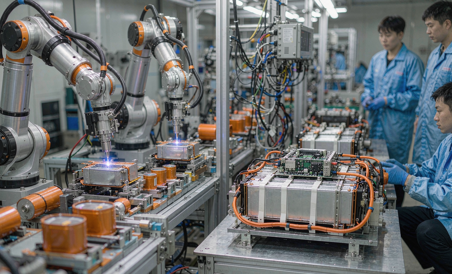
What Battery Solution Manufacturing Actually Means for Equipment OEMs
A cell is a commodity. A pack is a system. When an equipment OEM asks for a custom battery solution, what they are really buying is five deliverables bundled together: qualified cells, a mechanically survivable enclosure, a battery management system tuned to their duty cycle, a validated production process, and a compliance dossier. Drop any one of these and the product becomes a warranty liability.
In practice I split every equipment project into three specification layers before a single cell is ordered:
- Duty-cycle layer: continuous discharge current, peak current and its duration, daily cycle count, depth of discharge, ambient temperature range, and charge window. An AGV that runs 3 shifts at 0.8C continuous is a completely different pack from a survey drone that pulls 8C for 90 seconds.
- Mechanical layer: envelope dimensions, mounting method, ingress protection (usually IP54 for indoor equipment, IP65–IP67 for outdoor), vibration profile, and service access. Field-replaceable packs need connector cycles rated above 5,000 mating cycles.
- Regulatory layer: transport classification, target market standards, and end-of-life obligations. This layer decides testing cost and lead time more than any other.
Only after those three layers are frozen do we move to cell selection. Reversing that order is the single most expensive mistake I see in equipment programs, because a cell choice made too early forces compromises in every layer above it.
Cell Selection and Incoming Qualification: The Decision That Locks 80% of Performance
For equipment applications I typically evaluate three chemistries. LFP (LiFePO4) delivers 2,000–6,000 cycles at 80% depth of discharge with excellent thermal stability, at roughly 90–160 Wh/kg. NMC delivers 200–260 Wh/kg with 800–2,000 cycles, which is why weight-sensitive platforms and every high-drain drone battery still lean on it. Semi-solid-state cells are now entering pilot production for equipment that needs both energy density and a wider safe operating window, and we run them in qualification programs rather than volume builds until field data matures.
Incoming qualification is where a lithium battery program earns its reliability. Our standard receiving protocol for every cell lot:
- Open-circuit voltage sorting within ±5 mV across the build group. Anything wider and you are pre-loading imbalance the BMS will spend its life correcting.
- AC internal resistance (1 kHz) sorting within ±5% of lot median, plus DC internal resistance spot checks on 3% of the lot. IR outliers dominate heat generation and become the first cells to age out.
- Capacity grading on 100% of cells for critical applications, or statistical sampling (AQL 0.65) for cost-driven builds, with ±2% capacity spread inside a series string.
- Self-discharge screening after 14–21 days of storage at 25°C; we reject cells whose voltage drop exceeds 2× the lot mean, because micro-shorts show up here and nowhere else.
Each accepted lot gets a traceability record: cell manufacturer, production date code, lot number, and the grading data. When a field failure comes back 18 months later, that record is the difference between a two-day root-cause analysis and a six-week guessing game.
Inside the Line: Process Steps That Decide Pack Reliability
Assembly is not glue and wire. Every joint, every gap and every torque value is a controlled variable. Here is the process sequence we run for equipment packs, with the acceptance limits we hold.
Cell holders and spacing
For cylindrical builds (18650 and 21700) we use flame-retardant PC+ABS holders with a minimum 1.5 mm inter-cell gap for thermal decoupling. For prismatic LFP modules, compression fixtures hold cells at 200–400 kPa; too little and the cell swells and loses contact, too much and you accelerate mechanical stress on the jelly roll.
Welding
We use laser welding for nickel and nickel-plated-copper busbars, and resistance spot welding only for low-current tabs. Process control targets: joint resistance below 0.15 mΩ per weld, tensile pull strength above 30 N for 0.2 mm nickel strip, and zero penetration into the cell can. Every shift starts with a destructive weld coupon and a pull test; the data is logged against the batch. On high-current equipment packs above 100 A continuous we move to laser-welded copper busbars with a nickel interlayer, because pure nickel simply cannot carry the current without unacceptable I²R heating.
Insulation and mechanical integrity
Barley paper or fish-paper insulation on every cell top, silicone potting or structural foam where vibration exists, and a Hipot test at 1,500 V AC (or 2,121 V DC) for one minute between the pack terminals and the enclosure for systems above 60 V. Insulation resistance must exceed 100 MΩ at 500 V DC. Outdoor equipment packs then face IP validation and, where the customer’s platform demands it, a random vibration profile derived from IEC 60068-2-64.
Thermal design verification
We instrument prototype packs with 8–16 thermocouples and run the customer’s worst-case duty cycle. Acceptance: no cell surface above 55°C for LFP or 50°C for NMC at rated continuous current in a 35°C ambient, and cell-to-cell delta-T under 5°C. A 10°C delta across a module is not a cooling problem — it is a design problem, and it will halve your cycle life on the hot cells.
BMS Integration, Firmware Control and End-of-Line Testing
The BMS is the part of a custom battery solution that customers underestimate most. For equipment we specify per-cell voltage monitoring accuracy of ±10 mV, current sensing accuracy of ±1% of full scale, and at least two independent temperature sensing points per module. Protection thresholds are set against the cell datasheet, not against a generic template: typical LFP settings are 3.65 V overcharge cutoff with 3.55 V release, 2.50 V over-discharge cutoff, and charge inhibit below 0°C — that last one prevents lithium plating and is non-negotiable for equipment operating in unheated warehouses.
Balancing strategy matters as much as thresholds. Passive balancing at 50–150 mA is adequate for well-sorted cells in low-cycle applications. For multi-shift equipment I push for 300 mA+ passive or active balancing, because a 40 mV drift that never gets corrected turns into 8% usable capacity loss within a year.
Communication is where integration succeeds or fails. Most industrial equipment programs we support use CAN 2.0B (typically 250 or 500 kbps) or RS485 Modbus, with SMBus reserved for medical and instrumentation platforms. We deliver a signed protocol document and a firmware version register, so the OEM’s controller can verify the exact BMS build in the field.
Every pack then goes through 100% end-of-line testing before it leaves the line:
- Capacity verification at 0.5C discharge, accept ≥98% of rated capacity
- DC internal resistance measurement of the complete pack, logged against the batch baseline
- Full protection-function test: overcharge, over-discharge, over-current, short-circuit recovery, and thermal cutoff simulation
- Communication handshake test against the customer’s actual protocol
- Hipot and insulation resistance
- Final SOC set to 30–50% for shipping, per transport rules
Every result is stored against the pack serial number. That dataset is what makes a warranty claim solvable.
Compliance and Documentation: UN38.3, IEC 62133-2, IEC 62619 and UL 1973
Compliance is manufacturing, not paperwork bolted on afterwards, because several tests are destructive and must be scheduled against production samples.
- UN 38.3 (UN Manual of Tests and Criteria, Part III, 38.3): mandatory for all lithium battery transport. Eight tests — altitude simulation, thermal cycling, vibration, shock, external short circuit, impact/crush, overcharge, forced discharge. Any design change to cells, cell arrangement or enclosure triggers retesting. Budget 3–5 weeks.
- IEC 62133-2: safety for portable sealed secondary lithium cells and batteries. This is the baseline for handheld and portable equipment packs.
- IEC 62619: safety requirements for secondary lithium cells and batteries for industrial applications — the correct standard for AGVs, robots and industrial equipment, and it includes a propagation test that shapes your mechanical design.
- UL 1973 / UL 2271: required for stationary storage and light electric vehicle applications in North America. If your equipment sells into the US, confirm which one your buyer’s insurer expects.
- FAA and EASA rules: for any airborne platform or drone battery, watt-hour limits and state-of-charge rules for air transport (typically 30% SOC for cargo shipments of standalone cells and packs) govern how you ship, not just how you fly.
We ship every production batch with a document pack: UN 38.3 test summary, MSDS/SDS per GHS, CE declaration where applicable, packing instruction reference (PI 965/966/967 for air), and the pack’s own EOL test report. That set clears customs and satisfies audits; without it, product sits in a bonded warehouse.
Scaling from Prototype to Volume: Design for Manufacturing Lessons
Moving a design from 20 samples to 2,000 units a month exposes tolerances that a hand-built prototype hides. The DFM changes that repeatedly earn their keep:
- Design out hand-soldered wires. Replace them with FPC or PCB sense boards. A 13S pack with 14 hand-soldered sense leads has 14 failure opportunities per unit and no repeatable process capability.
- Give every fixture a keying feature. Asymmetric holders and polarized connectors make reverse installation physically impossible instead of merely unlikely.
- Standardize on two or three cell models internally. Volume purchasing on a small cell portfolio stabilizes supply, improves grading consistency, and shortens lead time from 8–10 weeks to 4–6.
- Freeze firmware before pilot production. Then treat every subsequent revision as a change-controlled event with regression testing. Undocumented firmware is the most common cause of “identical” packs behaving differently in the field.
- Build in a service path. Modular pack architecture lets a field engineer replace one module rather than scrap a 5 kWh assembly. This decision alone can cut lifetime service cost by 40%.
We also insist on a pilot run of 50–100 units under full production tooling before ramp. The pilot run is where process capability (we target Cpk ≥ 1.33 on weld resistance and capacity) is proven, and it is far cheaper to find problems there than in a customer’s warranty data.
Cost, Lead Time and What Equipment Buyers Should Ask
For a typical industrial equipment pack, cells account for 55–70% of BOM cost, the BMS 10–20%, enclosure and hardware 8–15%, and labour plus test the remainder. Cutting cost by downgrading the BMS is almost always the wrong move; cutting cost by simplifying the enclosure and reducing part count is almost always the right one.
Realistic timelines for a new custom battery solution: 1–2 weeks for specification and design review, 2–3 weeks for prototype build, 3–4 weeks for validation and thermal testing, 3–5 weeks for UN 38.3 and applicable safety certification (can partly run in parallel), and 4–6 weeks for first production. A disciplined program reaches volume shipment in 12–16 weeks; a program that changes specification mid-stream takes twice that.
If you are evaluating a manufacturer, ask for these five things and read the answers carefully: cell grading data for a recent lot, a weld pull-test log, the end-of-line test report template, the UN 38.3 test summary for a comparable pack, and the change-control procedure for BMS firmware. A supplier who produces all five within a day is running a controlled process. A supplier who cannot is selling you a sample, not a battery solution.
Frequently Asked Questions
What is the minimum order quantity for a custom battery solution for equipment?
For a fully custom pack with a new enclosure, tooling economics usually put the practical floor around 200–500 units per year, though prototype and pilot batches of 20–50 units are standard. If you need lower volumes, adapting an existing modular platform with custom firmware, connectors and labelling gets you 80% of the benefit at a fraction of the tooling cost.
Should I choose LFP or NMC for industrial equipment?
Choose LFP when cycle life, thermal safety and total cost of ownership dominate — AGVs, floor care, stationary equipment, telecom backup. Choose NMC when energy density and weight decide the product, which is why aerial platforms and high-drain handheld tools still use it. If your equipment charges opportunistically many times per day, LFP’s cycle advantage almost always wins on lifetime cost.
How long does UN 38.3 testing take and when must it be repeated?
Expect 3–5 weeks at an accredited lab. Retesting is required whenever the cell model changes, the cell arrangement or series/parallel configuration changes, the enclosure changes materially, or capacity/watt-hour rating changes beyond the allowed tolerance. Plan the test window into the program schedule rather than treating it as a final step.
What causes a well-designed lithium battery pack to fail early in the field?
In my experience the top four causes are cell imbalance from poor initial sorting, charging below 0°C without a heater or charge inhibit, connector and sense-wire fatigue from vibration, and thermal hot spots caused by inadequate inter-cell spacing. All four are manufacturing and design decisions, not cell defects.
Can one supplier cover drone, equipment and stationary storage packs?
Yes, and there is real engineering value in it — the high-rate discipline learned on a drone battery improves current-path design on industrial packs, while stationary-storage practice sharpens BMS diagnostics and cycle-life modelling. What matters is that the supplier applies the correct standard for each application: IEC 62133-2 for portable, IEC 62619 for industrial, UL 1973 for stationary, and transport rules for anything that flies.
If you are scoping a battery solution for equipment you manufacture, send us the duty cycle, envelope and target market, and we will return a design proposal with the test plan and compliance path attached. That is the document that tells you whether the project is real.





