
Battery Solution Performance for Robotics: A Senior
I am Karl Huang, Senior lithium battery Engineer at Horizon Power. Over the last decade I have specified, built and torn down battery solution designs for warehouse AMRs, inspection robots, agricultural platforms and last-mile delivery carts. And almost every robotics programme I join starts the same way: someone opens a spreadsheet, writes “we need 100 Ah”, and sends it to three suppliers.
That number is where the trouble begins. Amp-hours measure charge, not the thing a robot actually consumes. A robot consumes power over time in a shape — cruise draw, acceleration spikes, lift-motor bursts, hotel load for the compute stack, and regenerative braking that has nowhere to go when the pack is full. Two packs labelled “100 Ah” can differ by 60% in energy and by 300% in peak-current capability, and the robot only cares about the second one.
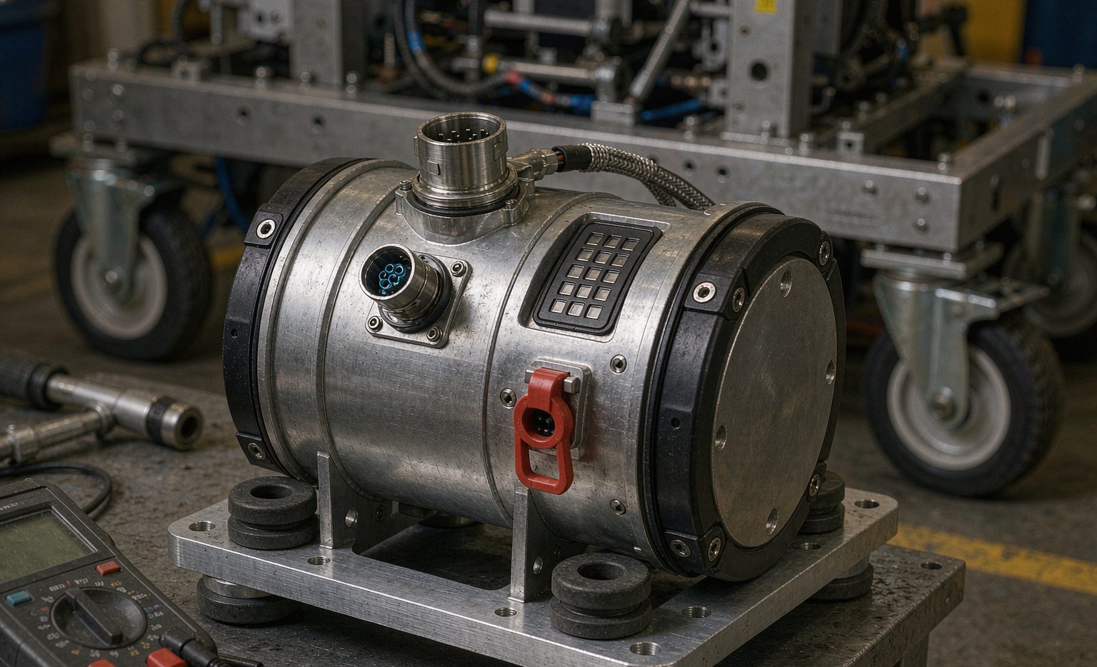
This article is the method I use in practice. It is not a product pitch; it is the measurement-and-specification workflow we run before a custom battery solution goes into tooling. If you take only one thing away, take this: performance for robotics is a duty-cycle power profile validated at temperature — everything else is marketing.
Why Amp-Hours Are the Wrong Starting Point
Amp-hours are a coulomb count. Robots run on watts and watt-hours, and they fail on volts. Three separate mistakes hide inside the “100 Ah” request.
- Ah hides voltage. A 10S LFP pack at 100 Ah is 32 V nominal, about 3,200 Wh. A 14S NCM pack at 100 Ah is 51.8 V nominal, about 5,180 Wh. Same number on the label, 62% more energy in one of them. Always quote Wh and the operating voltage window.
- Nameplate hides usable energy. You never get to drain a pack to zero. The BMS has an under-voltage release, the motor controller has its own UVLO, and you need a reserve for the last lift of the shift. A well designed lithium battery pack for mobile robotics typically delivers 85–92% of nameplate as usable energy in nominal conditions; a poorly matched one delivers 70% and the robot dies an hour early every day.
- Capacity hides power. A 100 Ah cell rated at 1C continuous cannot deliver a 4-second, 60 A lift burst without sagging. Energy gets the robot through the shift; power gets it over the threshold strip and up the ramp.
When a customer asks us for “100 Ah”, my first question is always the same: show me one hour of logged current from the robot. No log, no real specification — only a guess that will be renegotiated after the first pilot.
Build the Duty Cycle Before You Build the Pack
Every credible robotics battery application solution starts with a measured mission profile. Clamp a logging current shunt or a Hall sensor on the existing platform — or on a pilot unit with a temporary lead-acid or lithium battery pack — and record at a minimum of 10 Hz. If the robot has PWM-driven lifts or regenerative braking, record at 100 Hz, because the events that break things last under two seconds and a 1 Hz BMS log will average them into invisibility.
What a usable duty cycle contains
- Cruise/motoring current and its duty fraction
- Acceleration peaks: amplitude, duration, events per hour
- Actuator and lift bursts: amplitude, duration, events per hour
- Regenerative events: amplitude, duration, and whether the bus rises
- Hotel load: compute, lidar, radios, lights — typically 40–120 W continuous, and on a 24/7 AMR it is a larger share of daily energy than most teams expect
- Charging windows: how long, how often, and whether they are opportunity or overnight
A worked example
Here is a real-shaped 48 V warehouse AMR profile, reduced to one hour:
- Hotel load: 90 W continuous → 90 Wh/h
- Cruise: 250 W at 60% of the time → 150 Wh/h
- Acceleration: 2,200 W for 1.5 s, 72 events per hour → 66 Wh/h
- Lift actuator: 3,000 W for 4 s, 40 events per hour → 133 Wh/h
Total ≈ 439 Wh per hour. Over an eight-hour shift that is about 3,510 Wh, and with a 20% engineering margin the pack must deliver roughly 4,200 Wh usable, which lands near 4,800 Wh nameplate at 48 V — conveniently, about 100 Ah. The naïve number was right, but for the wrong reason: it would have been wrong for a robot with twice the lift frequency and identical “range requirements”.
Now the part that actually sizes the pack. Mean current is 439 Wh / 48 V ≈ 9.2 A. But heating scales with the square of current, so compute the RMS: the baseline of about 5 A for 93% of the hour contributes ~23 A², the 46 A acceleration bursts contribute ~64 A², and the 62 A lift bursts contribute ~171 A². RMS current ≈ 16 A, against a mean of 9.2 A. That ratio of 1.75 means the pack sees roughly three times the resistive heating that an average-current calculation predicts. Every thermal problem I have debugged in the field started with someone sizing to mean current.
Peak Versus Continuous: The Thermal Reality
Cell datasheets are honest but easy to misread. A cell rated “3C continuous, 5C for 10 seconds” is making a cell-level statement under defined cooling. A pack is limited by things the datasheet never mentions: busbar cross-section, weld quality, connector contact resistance, MOSFET RDS(on), and cell-to-cell imbalance at the moment of the spike.
What matters on a robot:
- Thermal time constant. A sealed 5 kWh pack has a thermal time constant of 20–40 minutes. A 4-second lift burst barely warms it; forty bursts per hour do. Design for the hourly energy of the spikes, not their instantaneous amplitude.
- Temperature budget. I target ΔT ≤ 15 K rise and a maximum cell temperature of 45–50 °C in continuous operation, with 60 °C as an absolute never-exceed. The reason is not safety margin alone — it is chemistry. Above roughly 30 °C, every additional 10 °C approximately doubles the calendar-aging rate. A pack that “works fine” at 60 °C is a pack you will replace in eighteen months.
- Peak derating rule. Keep continuous current at or below about one third of the peak rating unless you have measured the soak test. If the duty cycle needs more, get a bigger pack or a higher-power cell, not a braver protection threshold.
- Validate with a two-hour soak at maximum duty in a 40 °C chamber. Log cell temperature, terminal temperature and FET temperature separately; the hot spot is almost never where the thermistor is.
Sag, DCIR and the Brown-Out That Kills a Shift
The most common field complaint we get on robotics platforms is not “the battery ran out”. It is “the robot rebooted at 20% SoC”. That is a power problem masquerading as a capacity problem.
Sag is Ohm’s law: ΔV = I × Rpack. Internal resistance rises as the pack discharges and rises sharply as it cools. A 48 V system whose motor controller browns out at 40 V will reboot on a 62 A lift spike long before the pack is genuinely empty — because at 20% SoC and 10 °C the pack resistance may be 40–60% higher than it was at beginning of life.
How I measure DCIR
Use a 10-second pulse at 1–2C from a known SoC (I use 50%, 25 °C). Record ΔV/ΔI at 1 second (mostly ohmic) and at 10 seconds (ohmic plus charge-transfer). Both numbers matter: the 1-second value predicts reboot behaviour; the 10-second value predicts heating. Track them over the fleet’s life. In high-rate robotics service, power fade arrives before capacity fade — I treat 30–40% DCIR growth over BOL as the investigation trigger and 100% growth as end of life, regardless of what the capacity test says.
Design fixes, in the order I try them
- Raise the nominal voltage. More series cells means lower current for the same power, and sag scales with current.
- Reduce pack resistance: laser-welded nickel or solid busbars instead of spring contacts, torqued and re-checked terminals, adequate conductor cross-section.
- Stagger the loads. If the lift and the traction peak coincide, shift one by 200 ms in firmware — it costs nothing and removes the worst-case spike.
- Set the BMS under-voltage release above the controller’s UVLO by a deliberate margin. The BMS should shed the actuator gracefully; the controller should never be the thing that discovers the floor.
- Handle regeneration. On full charge, or at low temperature, braking energy raises the bus and the controller faults on the down-ramp. The BMS must permit a limited charge current, or the controller must taper regen by SoC and temperature. This is the same failure mode we see on mobility and drone platforms, and it is never found on the bench — only on the first long descent.
How I Test Before Signing Off
A specification without a test method is a wish. This is the sequence we run on every robotics programme before tooling sign-off.
- Nameplate capacity at 0.2C and 25 °C, following the conventions of IEC 62620 / IEC 61960. This is the only number that is comparable between suppliers, and it is not the number the robot will see.
- Duty-cycle replay. Drive the pack with the recorded mission profile on an electronic load or motor dyno, not a constant current. Constant-current tests hide every spike problem.
- Temperature corners. Repeat the replay at 45 °C, at 0 °C, and at −10 °C if the application sees freezers or outdoor winter work.
- Worst-case spike test at 80% depth of discharge, and again with a series resistor added to simulate end-of-life internal resistance.
- Charge acceptance including the actual opportunity-charging window (e.g. 15 minutes on a dock between missions).
Instrumentation and acceptance criteria
Four-wire voltage sense, a logger at ≥10 Hz (100 Hz for spikes), and thermocouples on the hottest cell — the geometric centre of the stack — plus terminals, busbar, FET area and ambient. Then compare what the bench sees with what the BMS reports. If current disagrees by more than 2%, or cell voltage by more than 50 mV, stop: you cannot trust the field data later, and field data is the only thing that will ever diagnose an intermittent fault.
Typical acceptance criteria I write into a contract:
- Usable energy ≥ 95% of nameplate at 0.2C, 25 °C, on a fresh pack
- Mission replay completes the full shift with ≥ 15% SoC reserve
- Minimum bus voltage during the peak spike ≥ controller UVLO + 3 V
- Maximum cell temperature ≤ 50 °C, terminal ≤ 70 °C
- No protection trip that was not a deliberate, documented design limit
Turning Measurements Into a Specification You Can Buy Against
Once the duty cycle and the corners are measured, write a performance specification — not a part number. This is the document that makes supplier quotes comparable, and it is the point at which battery pack design becomes an engineering exercise rather than a catalogue lookup.
- Nominal voltage and full operating window, with the controller’s UVLO stated explicitly
- Usable energy in Wh at a stated C-rate and ambient temperature
- Continuous current at 40 °C ambient with a stated ΔT limit
- Peak current profile: amplitude, duration, events per hour, and the maximum allowed sag
- DCIR at beginning of life, and the end-of-warranty growth limit
- Charging: CC-CV limits, opportunity-charge acceptance, and regenerative-charge acceptance
- Telemetry over CAN at ≥1 Hz: pack current and voltage, min/max cell voltage, at least two temperature points, SoC, and fault codes with a parameter snapshot
- Environment: IP rating per IEC 60529 (IP54 for indoor warehouse, IP65 if the robot is washed down), plus vibration and shock per IEC 60068-2-64 / -27
- Compliance documents: UN 38.3 test summary (mandatory for transport, and you must be able to produce it on request), IEC 62619 for industrial applications, IEC 62133-2 where the cell and pack fall in scope, and on the machinery side ISO 3691-4 for driverless trucks or ISO/TS 15066 if the robot works alongside people
A custom battery solution earns its cost when two or more of those lines are dictated by the site rather than chosen by you: the envelope is frozen by the chassis, the duty cycle sits outside every catalogue rating, the ambient range is permanently outside spec, or the BMS must close a control loop with your fleet management system. A protocol mismatch does not raise an alarm — it silently consumes 10–20% of your usable capacity, which is why I insist on a telemetry integration test before the first production pack ships.
Chemistry choice follows the profile, not the trend. High-power cells give up roughly 10–20% of their specific energy for the rate capability, and that is usually the right trade for a lift-heavy AMR. A semi-solid state battery design makes sense when the robot is energy-limited rather than power-limited and you need Wh/kg more than C-rate. A sodium-ion battery earns its place in cold-chain and outdoor stationary-adjacent platforms where low-temperature charge acceptance and cost matter more than energy density — but it still has to pass exactly the same duty-cycle replay. Changing chemistry does not exempt anyone from the measurement.
Field Performance: When Does It Actually Fail?
In the fleet, watch the metrics that move first. My minimum dashboard for a robotics programme:
- Watt-hours delivered per mission, temperature-normalised. Not amp-hours — Wh captures the sag losses that Ah misses.
- Peak sag at a fixed reference event (the same lift, at the same SoC, at the same temperature). This is the earliest honest signal of power fade.
- Cell voltage spread in mV at rest: below 50 mV is comfortable, 50–100 mV deserves investigation, above 100 mV isolate the module.
- DCIR trend measured quarterly at the same SoC and temperature.
Two operational notes that save programmes. First, opportunity-charged AMRs live in partial state of charge, which is genuinely gentle on LFP chemistry — but it starves both the balancing circuit and the SoC estimator. Schedule one full charge plus a two-hour rest per week so passive balancing can converge and the coulomb counter can recalibrate; without it, the fleet’s SoC readings drift by 10–15% and the robots start “randomly” dying at 25%. Second, hold spares at 5–10% of fleet size in year one and 3–5% afterwards, stored at 30–50% SoC in a cool room and rotated FIFO. Spares age on the shelf, and a spare that has sat at 100% SoC for a year is not a spare.
One last thing, borrowed from our drone battery fleet work: log everything. The pack that fails intermittently will never reproduce on the bench. The only way you will ever diagnose it is a fault code with a snapshot of current, cell voltages and temperatures at the moment it tripped.
Frequently Asked Questions
How do I size a battery solution for a robot if I have no prototype yet?
Build the duty cycle analytically from the mechanical design and then pad it. Estimate mass and rolling resistance for cruise power, use the lift-motor nameplate and duty for actuator bursts, add 40–120 W for compute and radios, and multiply the resulting Wh/h by the shift length. Then add 20–30% margin — not because the estimate is lazy, but because robots always gain payload, and added payload is paid for twice: once in energy and again in peak current.
Is a higher C-rate cell always the better choice?
No. High-rate cells trade 10–20% of specific energy for rate capability, and they typically cost more per Wh. If your duty cycle is hotel-load dominated, you are buying power you will never use and giving up runtime. Choose C-rate from the measured RMS current plus the peak profile, not from the highest number on the datasheet.
Why does my robot shut down with 20% SoC still showing?
Because the pack cannot deliver the spike at that SoC and temperature, so the bus collapses below the controller’s under-voltage lockout. Measure DCIR at 20% SoC and at the actual operating temperature, then either raise pack voltage, lower pack resistance, add a deliberate margin between the BMS release and the controller UVLO, or derate the actuator in firmware.
Can the same pack serve both opportunity charging and full-shift operation?
Yes, but the charging strategy has to be part of the specification. Verify charge acceptance in the real window, confirm that regenerative current is accepted at high SoC, and schedule a weekly full charge with rest so balancing and SoC calibration can converge. Also check that the connector and contactor are rated for the cycle count — on an opportunity-charged fleet, the connector becomes a wear item long before the cells do.
LFP or NCM for an AMR?
For a 48 V system, 15S LFP sits at 48 V nominal and matches legacy 48 V electronics beautifully, with two to four times the cycle life and a safer thermal profile; you give up energy density and you must respect the 0 °C charging limit. NCM at 14S gives 51.8 V and more Wh per kilogram, which matters if the robot is weight-limited. In my projects, indoor warehouse platforms almost always land on LFP; outdoor and weight-critical platforms justify NCM or a semi-solid design.
How often should we re-measure internal resistance?
Quarterly for a fleet in daily service, and always at the same SoC and temperature or the numbers are meaningless. In the first three months, measure monthly to establish the baseline — the shape of the early curve tells you more than any single reading.
What is the minimum telemetry a BMS solution should expose?
Pack voltage and current, min and max cell voltage, at least two temperature points, SoC, and fault codes carrying a parameter snapshot, all at 1 Hz or better over CAN. Below that, you are operating blind: every intermittent field fault becomes a pack swap instead of a diagnosis.
Do we need UN 38.3 if the packs never leave the site?
Almost certainly yes, because packs get returned for service, moved between facilities, and shipped as spares. UN 38.3 certification is a transport requirement, and since 2020 the test summary must be available on request for each cell and pack. It costs little to have and stops a shipment entirely when it is missing. Stationary safety is a separate question: industrial installations are covered by IEC 62619, with UL 1973 and UL 9540A in North American jurisdictions.





