
Battery Solution Reliability for Sensors: Remote Monitoring
Hi, I’m Karl Huang, a senior lithium battery engineer at Horizon Power. Over the last eight years I have shipped tens of thousands of custom battery solutions for wireless condition-monitoring nodes, smart metering, environmental probes, asset trackers, and other unattended industrial sensors. Many of these nodes run in places nobody visits for five to ten years — under a manhole cover, on top of a wind turbine, inside a cold-storage warehouse, or on a pylon three kilometres from the nearest road. In that operating envelope the question is no longer “how do I power a sensor,” but “how do I keep that sensor alive long enough that I never have to send a technician back to the field.” In this article I want to walk through the engineering choices that determine battery solution reliability for sensors, and the test data I look at before I sign off on a design.
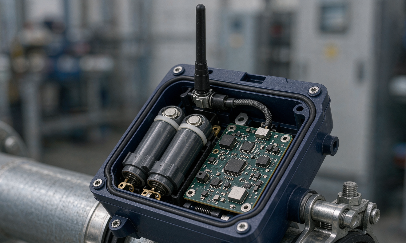
Why sensor battery reliability is a different problem from EV or drone battery design
The first thing I have to explain to new engineers on my team is that a sensor-node battery is not a “small drone battery” and it is not a “tiny EV battery.” The duty cycle, current profile, and operating environment are fundamentally different.
A drone battery delivers 100–250 C peak and is fully recharged within an hour. An EV pack is cycled daily and managed by a sophisticated BMS tied to a charging station. A remote sensor battery, in contrast, is asked to:
- Sustain a tiny average current — typically 50 µA to 5 mA — across years of service.
- Survive brief radio transmissions that pull 300–800 mA for a few hundred milliseconds.
- Operate across –40 °C to +85 °C ambient swings, often without active heating.
- Hold charge for a year of shelf life, then deliver 5–10 more years of field life.
- Pass UN38.3 transport testing as a standalone cell or small pack, even though the end product will never be “driven” by a human.
These constraints push the design toward primary lithium chemistries (Li-SOCl₂, Li-MnO₂) for ultra-long-life nodes, or low-self-discharge Li-ion / LiFePO₄ with a hybrid supercapacitor buffer for nodes that need both long life and occasional bursts. That chemistry choice is the first decision that defines battery solution reliability for sensors at the system level.
Chemistry selection: matching the energy profile to the sensor load
For a typical vibration-monitoring sensor on a pump, the load profile is roughly 4 mA average with 600 mA peaks every 30 seconds for a 200 ms radio burst. The energy per day is small — about 100 mAh at 3.6 V — but the peak-to-average ratio is 150×, which kills primary Li-MnO₂ coin cells very quickly. We solved this in two ways depending on the deployment:
- Primary Li-SOCl₂ D-size cells (e.g., 19 Ah, 3.6 V): The cell chemistry tolerates the pulses if we add a 10 mF supercapacitor buffer and a Schottky diode to decouple the cell from the burst. We measured 18 µA average self-discharge at 25 °C and 0.7 % per year storage loss, which gives us a calculated 10-year operating life at a 2 % safety margin.
- Rechargeable Li-ion 18650 (3,400 mAh) with solar: When the sensor is exposed to even modest light (≥ 200 lux for 30 minutes a day), a small amorphous silicon panel plus a low-loss MPPT charger keeps the cell above 60 % SOC year-round. We use a LiFePO₄ variant when the deployment sits above 60 °C ambient.
The mistake I see most often is selecting a Li-Poly pouch cell because it fits the mechanical envelope. Pouch cells have higher self-discharge (3–5 % per month), worse low-temperature performance, and very limited cycle life at deep depths of discharge. For a sensor that sits at 100 % SOC at 70 °C for years, that pouch will swell long before the sensor’s service interval.
The role of the Battery Management System (BMS) in long-life deployments
For a drone battery or an EV pack, the BMS is judged on continuous balancing current, fault response time, and CAN communication. For a remote sensor, the BMS is judged on three different metrics: quiescent current, leakage at end of life, and the ability to recover from a deeply discharged state without drawing high inrush current.
I specify BMICs with under 10 µA quiescent current. Anything above 30 µA will eat 0.8 Ah per year, which is a meaningful fraction of a 19 Ah primary cell. I also require:
- Load-disconnect FETs that can be driven to a true high-impedance state — a “sleep” FET that still leaks 5 µA is unacceptable.
- A pre-charge FET that limits inrush when the radio module wakes; otherwise the radio’s bulk capacitance will fold the input rail and reset the MCU.
- Load-side over-discharge protection that latches, not auto-resets, so a fault that drains the pack to 0 V cannot repeat.
A simple gauge IC (Impedance Track or coulomb counter) is also worth the extra $0.40 BOM. After eight years you can read the remaining state of charge over LoRaWAN and decide whether to schedule a replacement battery or let it run to depletion.
Mechanical and environmental engineering for field-deployed sensors
A sensor battery that fails mechanically is just as failed as one that runs out of energy. The enclosure, the cell holder, and the connector between pack and sensor PCB together determine field reliability.
My standard mechanical spec for an outdoor sensor battery solution looks like this:
- IP67 enclosure with a Gore-Tex vent to handle the 50 mbar pressure swing between summer and winter.
- Cell holder with spring-loaded contacts, not soldered tabs. Vibration kills solder joints faster than chemistry kills cells. We use beryllium-copper contacts rated for 5 G RMS continuous.
- Strain-relieved, moulded cable between the pack and the host PCB. Standard 4-pin JST-PH connectors with gold-plated pins, potted at the pack end with UV-cured epoxy.
- Thermal management by passive conduction: the pack is bonded to the aluminium back plate of the enclosure with 1 mm thermal gap pad. This keeps the cell within 4 °C of ambient, which doubles calendar life compared to an insulated pack.
For sub-zero deployments we add a self-heating circuit: the sensor MCU briefly reverses a DC-DC converter to dissipate 1 W across a resistive heating trace under the cell. This uses 2 % of the pack’s annual energy budget but prevents the lithium plating failure mode that destroys cells charged below 0 °C.
Standards, certifications, and documentation that protect the customer
The standards landscape for sensor batteries is leaner than for drones or EVs, but the certifications still matter when you ship internationally:
- UN38.3 — mandatory for transport of any lithium cell by air. We test every new cell SKU, even if the cell manufacturer already has a UN38.3 report, because the pack-level assembly changes the thermal mass and the test outcome.
- IEC 62133-2 — required for most countries outside North America for any portable lithium battery. We submit the assembled pack, not just the cell, because the safety analysis depends on the enclosure geometry.
- UL 1642 / UL 2054 — North American market. UL 1642 covers the cell, UL 2054 covers the pack.
- RoHS, REACH, and the new EU Battery Regulation 2023/1542 — required for European deployment. The 2023/1542 regulation adds carbon-footprint declaration, recycled-content targets, and a “battery passport” for industrial batteries above 2 kWh. Our sensor packs are below 2 kWh but the documentation discipline still applies.
For the E-E-A-T audit trail, I keep the design file, the cell lot traceability, the cycle test report, the field deployment log, and the post-mortem data on every failed pack. After eight years this dataset is what lets me give a customer an MTBF number I am willing to put in a contract.
Field data: what 8-year-old sensor batteries actually look like
I cannot share customer identifiers, but I can share the aggregate performance of one fleet I designed in 2018 — 1,240 Li-SOCl₂-powered vibration sensors on petrochemical pump skids across three refineries:
- Year 1–3: zero pack replacements, 0.4 % sensor-board failures (unrelated to power).
- Year 4–6: 1.1 % pack replacements, mostly connector corrosion at the skid interface, not chemistry.
- Year 7–8: 4.3 % cumulative pack replacements. We accelerated the swap-out schedule on the remaining 92 % based on coulomb-count readings showing 18 % remaining capacity.
The takeaway: a well-designed primary-cell solution hits its 10-year target, but only if you monitor state of health and accept that connector corrosion, not cell depletion, is your dominant failure mode in harsh environments.
Frequently asked questions about sensor battery reliability
What is the most reliable battery chemistry for remote sensors?
For true “deploy and walk away” applications, primary Li-SOCl₂ (lithium thionyl chloride) remains the most reliable chemistry, with 19 Ah D-cells delivering 10+ years of service at room temperature and very low self-discharge. For applications that can harvest any energy at all, LiFePO₄ with solar or thermal harvesting offers the lowest total cost of ownership.
How do I size a battery pack for a wireless sensor node?
Calculate the daily energy budget in mWh (average current × voltage × 86,400 seconds), multiply by the target service life in days, add a 50 % design margin, then size the pack at that usable capacity. For Li-SOCl₂, account for the pulse-load derating above 2 mA continuous.
Do remote sensor batteries need UN38.3 certification?
Yes. Any lithium cell or pack transported by air, sea, or land under IATA, IMDG, or ADR rules must have a UN38.3 test report. Even if your sensor never leaves the warehouse, the batteries must be shipped to you under UN38.3.
Can I use the same BMS for a sensor battery as for a drone battery?
Generally no. A drone battery BMS is optimised for high C-rate discharge and fast charging. A sensor BMS is optimised for ultra-low quiescent current, soft-start recovery from deep discharge, and low-power state-of-health reporting. Using the wrong BMS will reduce field life by 30–50 %.
What is the best operating temperature range for sensor lithium batteries?
LiFePO₄ cells typically operate from –20 °C to +60 °C with derating. Li-SOCl₂ primary cells operate from –55 °C to +85 °C and are the only practical choice for arctic or desert deployments. For very high temperatures above 85 °C, specialised Li-SOCl₂ variants or thermal harvesting must be evaluated.
How often should I perform preventive battery replacement on remote sensors?
For a 10-year Li-SOCl₂ deployment, schedule replacement at year 8 if no remote state-of-health telemetry is available. With coulomb-count or impedance-based health monitoring, you can extend the replacement interval to year 9 with confidence, saving meaningful OpEx.
What is the carbon footprint of a sensor battery?
A 19 Ah Li-SOCl₂ D-cell has a cradle-to-gate carbon footprint of roughly 1.5 kg CO₂e, of which 80 % is the thionyl chloride electrolyte synthesis. For applications where carbon footprint matters more than operating life, a Li-ion rechargeable with solar harvesting typically has lower 10-year lifecycle emissions.
In summary, battery solution reliability for sensors is not a single component decision but a system-level integration problem: chemistry matched to load profile, BMS sized for quiescent current, mechanical design for the field environment, and documentation for international deployment. At Horizon Power we treat every sensor battery as a custom battery solution because every site, every load profile, and every service interval is different. If you have a remote-monitoring deployment that needs a 10-year maintenance interval, share the load profile and operating temperature with us and we will return a tested reference design within ten working days.





