Lithium Battery BMS Architecture
In fifteen years of designing packs, I have learned that the cells rarely fail first. What fails is the system around them. When a customer sends me a field return that vented or shut down unexpectedly, the root cause almost always traces back to the protection electronics. Understanding lithium battery BMS architecture is therefore not an academic exercise for buyers and integrators; it is the difference between a pack that survives 2,000 cycles and one that becomes a warranty claim in six months. I am Karl Huang, a senior lithium battery engineer, and in this article I want to walk you through how a battery management system is actually built, layer by layer, from the sense wires to the firmware that decides when to open a MOSFET.
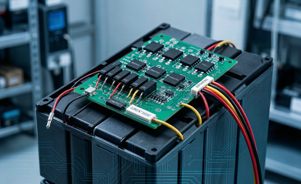
Every lithium battery pack we ship, whether it is a small 3S drone pack or a 15S industrial module, carries a BMS because a lithium cell has no built-in tolerance for abuse. Overcharge a single cell past roughly 4.25 V and you begin plating lithium metal on the anode; over-discharge below about 2.5 V and you dissolve copper from the current collector. Neither failure announces itself immediately, which is exactly why a well-architected BMS is the guardian that watches every cell, every second.
What a BMS Actually Does: The Three Core Jobs
Before diving into the hardware, it helps to define the mission. A BMS in any lithium battery has three fundamental responsibilities, and every architectural decision serves one of them.
- Protection. Prevent the cells from ever operating outside their safe voltage, current, and temperature window. This is the non-negotiable layer that keeps the pack from catching fire.
- Measurement and estimation. Accurately read cell voltages, pack current, and temperatures, then convert those raw numbers into meaningful values like state of charge (SOC) and state of health (SOH).
- Balancing. Keep individual cells at matched voltages so the weakest cell does not prematurely limit the entire pack’s usable capacity.
A cheap protection board might only do the first job. A proper BMS solution does all three, and does them with enough accuracy that the SOC reported to the user is trustworthy within a few percent. When I design a custom battery solution for an OEM, the conversation almost always starts with how sophisticated these three functions need to be for the target application.
The Hardware Stack: From Cells to Controller
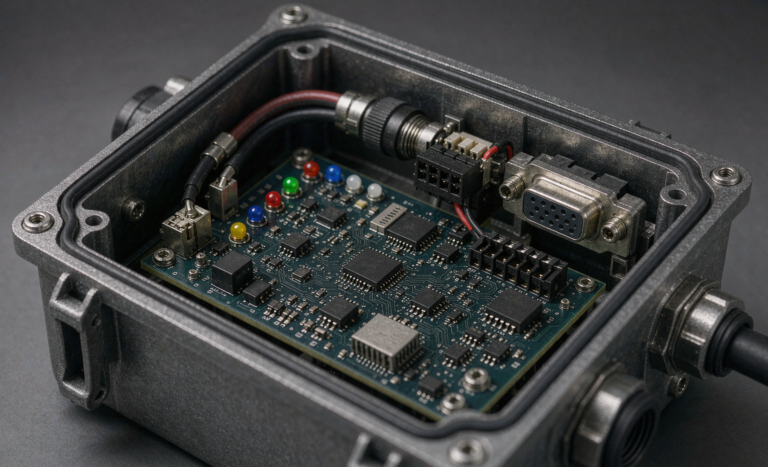
Physically, a modern lithium battery BMS architecture is a layered stack. Understanding each layer clarifies where cost, accuracy, and reliability come from.
Analog Front End (AFE)
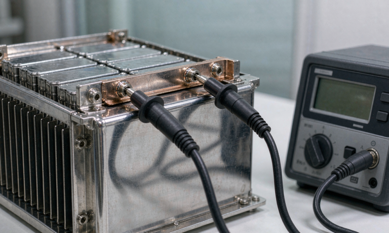
The AFE is the heart of measurement. It is a dedicated integrated circuit that connects directly to each cell tap through the voltage sense wires. In a 13S pack, that means fourteen sense connections. A good AFE, such as those built around the TI BQ769x0 or ADI/Maxim families, measures each cell voltage to within 1-2 mV and multiplexes those readings to the controller. The AFE also handles the raw comparators that trigger hardware overvoltage and undervoltage protection independently of any software. I always insist on Kelvin-style sensing on the sense wires so that current flowing through the wire does not corrupt the voltage reading, a detail that separates a professional pack from a hobby-grade one.
Current Sensing
Pack current is measured either with a low-value shunt resistor (typically 0.5 to 5 milliohms) or a Hall-effect sensor. The shunt is more accurate and cheaper but dissipates heat at high current; the Hall sensor is isolated and lossless but drifts with temperature. For a high-drain lithium battery pack, I usually specify a shunt paired with a precision amplifier because coulomb counting for SOC depends entirely on integrating this current accurately over time.
Protection MOSFETs
The main switching element is a back-to-back pair of power MOSFETs in the charge and discharge path. One FET blocks discharge current, the other blocks charge current, and together they let the BMS cut the pack off in either direction. Selecting these FETs is a thermal exercise: at 50 A continuous, even a 2 milliohm on-resistance dissipates 5 W per device, so heatsinking and gate drive matter enormously. This is one area where a rushed design fails in the field.
Microcontroller and Firmware
Sitting above the AFE is the microcontroller (MCU) running the firmware. This is where the intelligence lives: SOC algorithms, SOH tracking, communication protocols, and the decision logic that decides whether a fault is transient or genuine. In premium designs, the MCU acts as a second, independent protection layer on top of the AFE’s hardware comparators, giving you redundancy that safety standards increasingly expect.
Cell Balancing: Passive vs Active Architecture
No two cells are perfectly identical. Even Grade A cells from the same batch differ slightly in capacity and internal resistance, and those differences grow with age. Without balancing, the pack’s capacity is dictated by whichever cell hits the voltage limit first. This is why balancing architecture is such a defining feature of any lithium battery BMS architecture.
Passive balancing is the workhorse. When a cell rises above its neighbors during charge, the BMS switches a bleed resistor across it, burning off the excess energy as heat until the others catch up. It is simple, cheap, and reliable, and it is what I specify for perhaps 90% of packs. The downside is that it only works during charging and wastes energy, with typical balancing currents of 50-200 mA.
Active balancing moves charge from stronger cells to weaker ones using inductors or capacitors, wasting far less energy and working during both charge and discharge. It is significantly more expensive and complex, so I reserve it for large-format energy storage or applications where every watt-hour of usable capacity is critical. For most B2B customers, honest engineering means telling them that active balancing rarely pays for itself unless the pack is very large or the duty cycle is extreme.
Communication: How the BMS Talks to the World
A modern BMS is not a black box. It reports its state to a host system so that a charger, an inverter, or a fleet management platform can make informed decisions. The communication layer is a core part of the architecture, and the protocol choice depends on the application.
- I2C or SMBus for small consumer and portable packs, where the BMS behaves like a smart battery reporting SOC and health to the host device.
- CAN bus for automotive, industrial, and energy storage systems, prized for its noise immunity and multi-node capability. Most of the industrial custom battery solution work I do standardizes on CAN.
- RS485 or UART for stationary storage and telecom, where simple, robust, long-distance links are needed.
Getting the communication architecture right early is essential. I have seen integration projects stall for weeks because a pack reported SOC over a protocol the inverter could not parse. A good battery solution provider defines the data map before the first prototype is built.
Safety Redundancy and Compliance
The reason lithium battery BMS architecture has grown so layered is safety. A single point of failure is unacceptable in a device that stores this much energy. In a robust design, protection happens at three independent levels: the AFE hardware comparators, the MCU firmware logic, and often a secondary standalone protection IC that acts as a last-resort backstop. If the firmware hangs, the hardware still cuts the pack off.
This layered approach is what safety certifications demand. Every pack we build is validated against UN38.3 for transport safety, which includes overcharge and forced-discharge abuse tests that directly exercise the BMS protection thresholds. Cells and packs also target IEC 62133 for consumer applications, and for anything that flies, the BMS must respect the state-of-charge and packaging rules laid out by the FAA and EASA for lithium battery air transport. When I set protection thresholds in firmware, I am not choosing arbitrary numbers; I am building in the margin those standards require.
How Architecture Choices Change by Application
There is no single correct BMS. The right architecture is the one matched to the load profile, environment, and cost target. A drone lithium battery prioritizes low weight and high discharge current, so its BMS uses lightweight FETs and minimal balancing to save mass. A home energy storage pack prioritizes cycle life and accurate SOC over a decade, so it justifies a more elaborate AFE and richer telemetry. A telecom backup pack prioritizes reliability and long float life, so its firmware emphasizes gentle charging and precise SOH tracking.
This is exactly why an off-the-shelf protection board so often disappoints. When we develop a custom battery solution, we tune every layer of the architecture, from the shunt value to the balancing current to the CAN message set, around what the customer’s product actually does. The cells might be commodities; the BMS is where the engineering value lives.
Frequently Asked Questions
What is the difference between a BMS and a simple protection circuit module (PCM)?
A PCM only provides basic overvoltage, undervoltage, and overcurrent cutoff. A full BMS adds accurate SOC and SOH estimation, cell balancing, temperature management, and communication. Think of a PCM as the seatbelt and a BMS as the entire safety and instrumentation system of the car.
Can I reuse the same BMS across different lithium battery packs?
Only if the packs share the same cell count, chemistry, current rating, and connector layout. Even then, the firmware protection thresholds should be re-validated. Reusing a BMS designed for a lower-current pack in a high-drain application is a common cause of overheating FETs.
How accurate is the SOC reported by a good BMS?
A well-designed BMS combining coulomb counting with periodic voltage-based correction typically reports SOC within 3-5% across most of the operating range, tightening near the full and empty endpoints. Accuracy degrades over the pack’s life unless SOH tracking recalibrates the capacity estimate.
Does active balancing really extend battery life?
It extends usable capacity more than lifespan directly. By keeping cells matched, it prevents the weakest cell from being over-stressed, which indirectly helps longevity. For most packs, however, quality passive balancing with well-matched cells delivers the majority of the benefit at a fraction of the cost.
What happens if the BMS firmware crashes mid-flight or mid-cycle?
In a properly architected system, the independent hardware protection layer in the AFE or a secondary protection IC continues to enforce voltage and current limits even if the firmware hangs. This redundancy is precisely why we never rely on software alone for critical protection.