Lithium Battery Testing for Mobility Devices
Every lithium battery for mobility devices we ship leaves the building with the same promise: it will not let a person down when they are halfway across a parking lot. In my fifteen years as a senior lithium battery engineer at Horizon Power, I have learned that “reliable” is never a feeling—it is the sum of a test plan. Reliability (how a pack ages in the field) is the outcome; testing is the discipline that proves the outcome before a single unit reaches a wheelchair user. This article is the validation protocol I run on every lithium-ion battery pack destined for a mobility device, from electric wheelchairs to power-assisted scooters. The same UN 38.3 and IEC 62133 discipline we apply to a drone battery pack applies here too, only with a higher safety bar because a rider cannot simply step off.
Why Mobility-Device Testing Deserves Its Own Protocol
Mobility devices are safety-critical in a way consumer electronics are not. A phone lithium battery fails and you lose a call. A battery pack for a mobility device fails and a person is stranded. That difference shapes the entire test plan. The duty cycle is stop-start: long idle at partial state-of-charge, sudden 50–70 A hill-climb surges, regenerative braking, and temperature swings between an indoor charger and an outdoor ramp. On top of the physics, the category is regulated. ISO 7176 governs powered wheelchairs, IEC 60601-1 treats the battery as a medical electrical device component, and UN 38.3 is mandatory for transport. A generic consumer-cell test sheet does not touch any of these, which is why we build a protocol specific to the application rather than reusing a one-size-fits-all checklist.
Step 1 — Incoming Cell Grading (Build the Foundation)
The single biggest predictor of pack life is cell uniformity, and you cannot fix it after assembly. Before a cell ever enters a pack, we grade it on three axes:
- Capacity grading: sort cells into ≤1% capacity bins; pack-level capacity coefficient of variation (CoV) must stay under 6%.
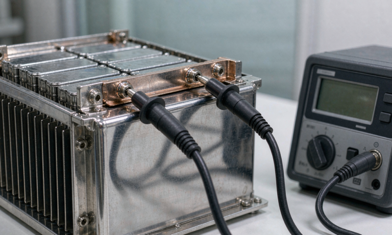
- 4-wire Kelvin DCIR: measure direct-current internal resistance with a Kelvin fixture to remove lead resistance; pack DCIR CoV under 10%. Cells that drift here imbalance within 30 cycles.
- K-factor self-discharge: store at 45 °C for 7 days and measure open-circuit-voltage drop; reject anything above 1.0 mV/day. A high-K cell is a slow bleed that kills balance and triggers false faults.
The reason grading is non-negotiable for a lithium ion battery is lot-to-lot chemistry drift. Even cells from the same datasheet can differ 3–5% in real capacity and 8–12% in DCIR between production lots. Without sorting, the weakest cell in a 10S pack becomes the pack’s true capacity ceiling and the first to over-discharge. We have torn down returned mobility packs where a single ungraded cell had dropped to 78% of its siblings—the whole pack was condemned for one weak link.
Every cell carries a DataMatrix genealogy code so a field return can be traced to its grade bin. This is where a custom battery solution earns its keep—off-the-shelf packs skip grading and ship the imbalance straight to the customer. We have seen name-brand mobility packs fail within a season purely because the cells were never matched.
Step 2 — Pulsed Functional Testing (Replay the Real Duty Cycle)
A pack that passes a steady 1C discharge can still collapse under a mobility device’s real current profile. We record the device’s current trace—typically 15–30 A cruise, 50–70 A ramp on a grade, 120–350 Wh per day for a wheelchair—and replay it on the bench at 1.2× severity.
Capturing that trace is itself a step. We instrument the device with a hall-effect current shunt and a datalogger, then have a clinician and a real user run a representative day—home to clinic to supermarket—so the replay includes elevator waits, ramp launches, and the long idle while charging at a desk. A synthetic sine wave would miss the 200 ms current spikes that actually stress the busbars. Two gates matter:
- Bus-voltage sag: under the 70 A peak the pack terminal must stay above the BMS low-voltage cutoff with a programmed reserve (we target <8% sag at the center cells). If it dips, the wheelchair stutters mid-hill.
- Thermal read: infrared scan of the center cells during the pulse; ΔT across the pack must stay under 8 °C. Hot centers are exactly where thermal runaway starts.
We also verify the fuel gauge: SoC error must read within 3% against a coulomb-count reference after the replay, or the user gets a false “low battery” stranding. A lithium battery pack that lies about its own charge is worse than one with less capacity.
Step 3 — Abuse Qualification (Prove It Survives)
Before mass production a sample lot goes through full abuse qualification. The backbone is UN 38.3 T.1–T.8: altitude (simulated 15,240 m), thermal (rapid −40 → 75 °C), vibration, shock, external short circuit, impact/crush, overcharge, and forced discharge. We add IEC 62133-2 (portable cells) and IEC 62619 (industrial), plus nail-penetration and crush tests with a no-propagation criterion—one cell may fail, the pack must not chain-react. Chemistry choice drives the margin here: lithium iron phosphate (LFP) has a thermal-runaway onset near 270 °C versus roughly 210 °C for NMC, which is why we default to LFP for anything a person rides. UL 2580 rounds out the mobility safety case and is the standard most OEMs ask for by name.
No-propagation is the clause I care about most for a rider. A wheelchair user sits on top of the pack for hours; if one cell goes into thermal runaway, the difference between a smoldering seat and an evacuable one is whether the other cells join in. Our barrier design—aerogel pads plus directional venting—is validated by the nail test, not by a spreadsheet.
Step 4 — Environmental Stress Screening
A mobility device lives outdoors. Our ESS sequence: thermal cycling from −10 to 60 °C for 20 cycles, random vibration to MIL-STD-810H Method 514.8, mechanical shock to Method 516.8, a 2 m drop on each face, and an IP54/IP65 spray test depending on the enclosure rating. Connectors get an insertion-cycle test to confirm the rated life, and for coastal or beach-wheelchair use we add salt-fog per IEC 60068-2-52. The point of ESS is not to pass once—it is to surface latent defects (cold solder, cracked potting, a loose busbar) before they reach a user. We budget roughly 5% scrap at this stage; that scrap is the cheapest insurance the program buys.
Step 5 — BMS Functional Test and the End-of-Line Gate
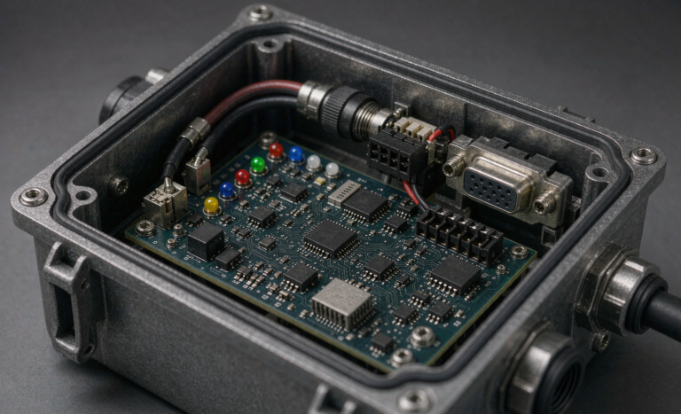
The battery management system is the part that actually keeps the promise. On the test bench we exercise: layered over-current protection (we validate trip below 200 ms at the rated 60 A), short-circuit protection, pre-charge to limit inrush, contactor weld-detection, and a charge lockout below 0 °C to stop lithium plating. The fuel gauge, balancing (we target 20 mV cell-to-cell), and the non-volatile fault log are all checked. Finally, the end-of-line gate: every pack must show ≥98% of nameplate capacity, DCIR within +10% of grade, and a cell-voltage spread ≤30 mV. Anything outside that window is torn down, not shipped. A DataMatrix on the finished pack closes the genealogy loop from individual cell to final product, which is what lets a custom battery solution stay serviceable for a decade.
One detail engineers underestimate: the test record is a product. Each pack ships with a digital birth certificate—grade bins, ESS results, BMS firmware hash, and the EOL gate numbers—so a service tech ten years later can see exactly what left the factory. For a lithium battery pack that may outlive two wheelchair frames, that paper trail is what makes a custom battery solution serviceable instead of disposable.
From Qualification to Fleet Pilot
A passed qualification is necessary but not sufficient. Before a full production run we place 5–10 packs into a 90-day fleet pilot with a partner clinic or wheelchair service. We watch real returns, real charge habits, and real thermal exposure. If the pilot shows fade under 2% at 110 cycles and zero thermal events—our standard bar—we release the build. If not, the test plan earns its cost by stopping a bad design before it scales. That is the whole point of lithium battery testing for mobility devices: turn “I think it is safe” into “I proved it.” The same method scales from a single wheelchair pack to a thousand-unit lithium battery pack order without changing a single gate.
Frequently Asked Questions
How is lithium battery testing for mobility devices different from e-bike testing?
Mobility devices are often medical-class (ISO 7176, IEC 60601-1) and safety-critical for a rider who cannot easily walk away, while e-bikes follow consumer transport standards such as EN 15194. The test severity and the no-propagation abuse bar are higher for mobility, and the fuel-gauge accuracy requirement is tighter because a false reading strands a person rather than just an ebike commuter.
What standards apply to a lithium battery pack for a wheelchair?
The minimum stack is UN 38.3 (transport), IEC 62133-2 (cells), IEC 62619 (industrial pack), UL 2580 (mobility safety), ISO 7176 (wheelchair system), and IEC 60601-1 if it is a medical device component. Regional marks such as CE and FCC layer on top depending on the market.
How long does a full qualification take?
Cell grading and a single prototype lot run about 2–3 weeks. Full abuse qualification with environmental stress screening and the 90-day fleet pilot extends to roughly 4 months, though we compress the calendar by running ESS and functional tests in parallel on separate samples.
Can the same test plan be used for a custom battery solution?
Yes. The protocol is chemistry- and form-factor-agnostic. A custom battery solution only changes the duty-cycle replay file and the enclosure ESS profile; the cell grading, abuse qualification, BMS functional test, and end-of-line gates stay identical regardless of shape or capacity.