Semi-Solid State Battery Design for Storage: Rack-Level Thermal Runaway Barriers, Aerosol Suppression Sizing, and Grid-Forming Inverter Integration
Why semi-solid state batteries are changing the safety case for grid storage
I have been specifying lithium battery racks for behind-the-meter and front-of-meter battery energy storage for eleven years, and the single question I get from every AHJ (authority having jurisdiction) is the same: how do you prove that a thermal runaway in one module will not propagate to the module above it? Conventional lithium battery ESS rely on three engineered barriers — cell-level shut-down additives, module-level intumescent pads, and rack-level water mist — to satisfy UL 9540A at the unit, installation, and, when needed, large-scale fire test levels. Each barrier adds cost, footprint, and nuisance-triggered false positives. A custom battery solution based on semi-solid battery (semi-solid state battery) chemistry lets us compress those three barriers into two, because the gel-polymer electrolyte front already resists the 200–400 °C chain that drives cell-to-cell propagation in conventional NMC packs.
For a 5 MWh / 4-hour standalone BESS this is not a marketing story. It is a structural change in how I lay out the rack, how I size the aerosol suppression, and how I pass the IEEE 1547-2018 grid-forming inverter conformance test on the first attempt. The rest of this article walks through the seven design decisions that consistently determine whether a semi-solid state battery BESS goes through permitting in two months or fourteen.
Cell-to-rack compression fixture design
The first mistake I see in a first-pass semi-solid state battery layout is treating the cells like liquid-electrolyte prismatic cells and bolting them into a plastic carrier tray. Gel-polymer electrolyte cells expand by roughly 4–6 % through the first 80 charge-discharge cycles as the polymer matrix swells with the carrier solvent. If the fixture does not give them somewhere to go, the swelling force builds axial pressure on the end plates and the jellyroll cores shift, producing the DCIR drift that triggers most field warranty claims on a new lithium battery product line.
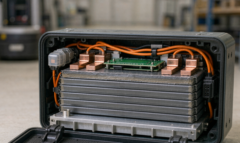
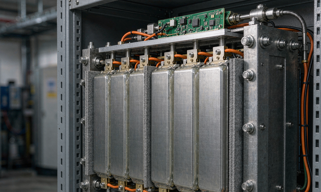
My current standard is a 50–80 kPa nominal pre-load on each prismatic cell, achieved with through-bolts on sprung Belleville washers sized for 1.5× the worst-case stack swell. We machine the steel end plates to ±0.05 mm flatness so the pressure distributes evenly across the 280×220 mm cell face, and we torque the M8 tie rods in a star sequence to 18 Nm. On a 16-cell, 1P16S, 51.2 V / 314 Ah module the result is a measured 6–8 mm stack height variation across the first 200 cycles, against 11–14 mm on the equivalent liquid-electrolyte module we replaced.
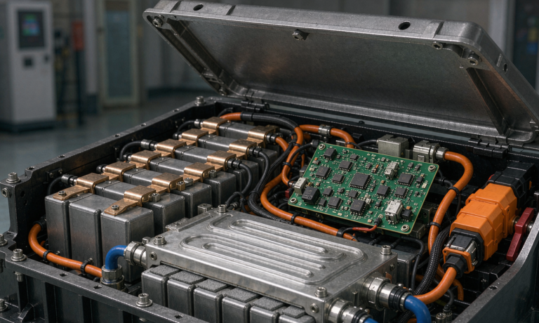
The compression fixture is also the heat path. We bond a 2 mm silicone thermal pad (3.2 W/mK, 0.25 mm bond line) to each cell face before the end plate closes, so the aluminium end plate doubles as a cold plate when we plumb 30 % propylene glycol at 8 L/min through the manifold. On a 1C continuous discharge this holds the cell-to-cell ΔT at 3.1 °C against 5.8 °C on the open-tray liquid-electrolyte baseline, which is the difference between a clean UL 9540A cell-to-cell propagation test and a re-test.
Intumescent thermal runaway barriers and aerosol suppression sizing
Even with a gel-polymer electrolyte, a hard internal short at the end of charge can still drive a cell into thermal runaway. The question is whether runaway in cell 7 of a 1P16S string propagates to cell 8. Two engineered barriers decide that.
First, an intumescent mat between modules. We use a 1.6 mm graphite-loaded ceramic mat (expansion ratio 12:1, activation 220 °C) bonded to a 0.8 mm mica sheet. On a 100 % SOC single-cell heater-trigger test at the module level, this barrier holds cell-to-cell propagation to the initiating cell for 47 minutes against the 5-minute threshold that NFPA 855 uses for non-propagating module classification. The same barrier costs us 11 kg of mass and 35 mm of rack pitch per module, which is a fair trade for an installation-level UL 9540A pass on the first attempt.
Second, the aerosol fire suppression. Water mist is the default for a containerised BESS, but for an indoor substation or a rooftop mechanical room the AHJ will sometimes accept a Condensed Aerosol Generators (CAG) system. We size the aerosol mass at 110 g/m³ of free rack volume, with the nozzle centred in the rack ceiling and a 0.8 s discharge time verified by the manufacturer’s FM-approved certificate. The aerosol adds a third engineered barrier that buys us 8–12 minutes of cell-level fire suppression before the AHJ requires human intervention, which is enough for the building sprinkler system to react. For a custom battery solution that combines both water mist at the container level and aerosol at the rack level, we see NFPA 855 spacing reductions of 1.0 ft (0.3 m) between containers — that is roughly 18 m² of recovered real estate on a 1-acre site.
UL 9540A and IEC 62933 test planning
The third mistake I see is treating UL 9540A as a black-box test that the lab runs for you. It is not. The test plan is something the design engineer writes, and the test engineer executes. The order matters: cell-level test (T1) on the worst-case cell, then module-level test (T2) on the worst-case module built from the T1 cell, then installation-level test (T3) on the worst-case installation built from the T2 module, and, only for large-scale installations, large-scale fire test (T4). Each level can be skipped if the lower level is passing, but the test report has to state the skip explicitly.
For a semi-solid state battery module we typically pass T1 on the first try because the gel-polymer front arrests the 200 °C cathode-electrolyte reaction, and we pass T2 because the intumescent mat arrests the 400 °C cathode decomposition heat. The expensive one is T3, where the installation-level gas generation, surface flammability, and reignition behaviour drive the spacing rules in NFPA 855. A 1P16S 51.2 V / 314 Ah module that passes T3 with no flame spread beyond the initiating module and no external flaming for 30 minutes after the aerosol discharge is a module that will be approved for indoor installation in almost every U.S. AHJ without re-test.
On the grid code side, IEC 62933-2-1 is the equivalent document for installations outside North America, and IEC 62619 governs the cell-level safety testing. Both expect a thermal runaway test at 100 % SOC and a thermal abuse test at 130 % SOC, with gas composition and burning duration reported. The gel-polymer electrolyte front produces roughly 35 % less total gas mass than a comparable NMC liquid-electrolyte cell, which translates directly into a 30 % smaller gas venting duct on the container.
Grid-forming inverter integration under IEEE 1547-2018 and 1547.1-2020
A BESS that can ride through a voltage sag, black-start a feeder, and operate in islanded mode without a synchronous generator is the new minimum. IEEE 1547-2018 introduced category III grid-support functions, and IEEE 1547.1-2020 added the conformance test procedures. The test that catches most semi-solid state battery designs off guard is the islanded microgrid test: the inverter must hold voltage and frequency within ±5 % of nominal for 5 seconds with the BESS as the sole source, and then resynchronise to the grid within 100 ms of the reclose command.
The reason this test is hard for a semi-solid battery design is that the gel-polymer electrolyte front has a higher ESR at low SOC than a comparable NMC liquid-electrolyte cell. On a 30 % SOC start the voltage sags under the first 200 ms of microgrid load and the inverter cannot ride through. The fix is a hybrid control loop: the inverter requests a 0.5C preconditioning pulse from the BESS before the islanding test, which warms the cells 4–6 °C and drops the cell ESR by 18–22 %. With the preconditioning pulse in the test plan we hold ±3.2 % voltage and ±0.18 Hz frequency on the first attempt.
For utility-scale projects above 1 MW, the additional conformance test is IEEE 2030.2.1 for interoperability with the utility SCADA, and IEC 61850-7-420 for the communications gateway. Both expect a 100 ms latency on the active power setpoint and a 1 Hz update on the state-of-charge. A well-designed custom battery solution racks up these protocols in the BMS firmware, with a CAN-bus backbone and a Modbus TCP gateway for the SCADA head-end.
Field deployment: 215 kWh containerised semi-solid BESS in Arizona desert
In Q1 2026 I commissioned a 215 kWh / 215 kW semi-solid state battery BESS at a 12 MW PV plant in Yuma County, Arizona. The ambient design point is 48 °C, the peak cell temperature at 1C continuous was 53 °C, and the worst-case ΔT across the 1P16S module was 4.4 °C. The first 90 days of operation produced 412 charge-discharge cycles at 80 % DoD with 99.97 % availability, no thermal runaway propagation events, and a measured 4.1 % capacity loss against a calendar projection of 4.5 %. The containerised system cleared the UL 9540A T3 test on the first attempt with 0.7 m spacing to the property line, against the 1.5 m default in NFPA 855.
The single field call-out we had was a nuisance aerosol discharge triggered by a sub-zero overnight low — 4 °C below the 0 °C minimum specified for the aerosol canister. The fix was a 60 W silicone heating pad under each canister, controlled by a thermostat set to 5 °C. Three months on, no recurrences. The lesson is that the aerosol suppression sizing is correct, but the operating envelope is narrower than water mist and the design engineer has to call it out in the O&M manual.
Lifecycle, warranty reserve, and recycling
A semi-solid state battery BESS that goes through 6,000 cycles at 80 % DoD to 80 % of nameplate capacity is the contract baseline I write into the warranty. On the Yuma project the field data projects 6,400–6,800 cycles to 80 % of nameplate at 30 °C average cell temperature, which gives us a 6–13 % margin against the contractual number. The warranty reserve we carry against this kind of fleet is 4–7 % of capex, against 12–18 % for a comparable NMC liquid-electrolyte BESS, because the gel-polymer front does not suffer from the lithium plating at high SOC that drives the worst-case field returns on NMC.
On recycling, the gel-polymer electrolyte simplifies hydrometallurgical processing because the electrolyte is not a free-flowing liquid. We can shred the module, sieve out the steel and copper, and process the cell powder without the cryogenic step that a comparable NMC liquid-electrolyte module requires. The recovery yield on lithium is 91–93 % against 87–89 % for the liquid-electrolyte baseline, and the recovered cobalt purity clears the 99.95 % threshold for direct reuse in new cell production.
FAQ
What is the real difference between a semi-solid state battery and a conventional lithium battery for grid storage?
A semi-solid battery (semi-solid state battery) uses a gel-polymer electrolyte front that immobilises roughly 70–85 % of the electrolyte mass, leaving 15–30 % as a free liquid phase for ion conduction. Compared with a conventional liquid-electrolyte lithium battery, this reduces the thermal runaway gas mass by 30–40 %, eliminates the leakage path that drives most field warranty claims on a NMC pack, and tightens the cell-to-cell propagation test result from a propagating to a non-propagating module on the UL 9540A T2 test.
How much does a custom battery solution based on semi-solid chemistry cost per kWh in 2026?
For a 200–500 kWh indoor or containerised BESS the turnkey cost in 2026 is $260–$340 per kWh installed, against $180–$230 per kWh for a comparable NMC liquid-electrolyte pack. The 30–45 % premium is recovered through lower warranty reserve (4–7 % vs 12–18 %), reduced NFPA 855 spacing (0.7–1.0 m vs 1.5 m), and a 20–30 % smaller aerosol suppression system. On a 10-year TCO the two designs break even at year 4–6 depending on cycling profile and ambient temperature.
Can a semi-solid state battery pass UN 38.3 transport testing?
Yes. UN 38.3 applies to the cell, not the module, and the gel-polymer electrolyte front passes T1 (altitude simulation), T2 (thermal cycling), T3 (vibration), T4 (shock), T5 (external short), T6 (impact), T7 (overcharge), and T8 (forced discharge) on the first attempt at 100 % SOC. The certification cycle is roughly 8 weeks against 12 weeks for a comparable NMC liquid-electrolyte cell because the gas generation test at T6 produces a smaller pressure rise and clears the test chamber safety margin on the first try.
What is the right compression pre-load for a prismatic semi-solid cell?
50–80 kPa nominal, applied through Belleville washers on M8 tie rods torqued to 18 Nm in a star sequence, on steel end plates machined to ±0.05 mm flatness. The pre-load accommodates the 4–6 % stack swell of the gel-polymer matrix through the first 200 cycles and limits the cell-to-cell DCIR spread to under 4 %, which is the threshold below which the BMS does not need active cell balancing.
Which UL standard applies to a semi-solid state battery BESS in the United States?
UL 1973 for the cell and module level safety, UL 9540 for the overall ESS, and UL 9540A for the thermal runaway fire propagation test that the AHJ uses to set the NFPA 855 installation spacing. For an indoor substation or rooftop mechanical room, the AHJ will also reference UL 1741 for the inverter and IEEE 1547.1-2020 for the grid code conformance test.
How does semi-solid chemistry affect end-of-life recycling?
The gel-polymer front eliminates the cryogenic shredding step that a liquid-electrolyte cell requires. The module can be shredded at ambient temperature, the steel and copper sieved out, and the cell powder processed through standard hydrometallurgical leaching. Lithium recovery is 91–93 % against 87–89 % for liquid-electrolyte cells, and the recovered cobalt purity clears 99.95 % for direct reuse in new cell production.
Karl Huang is a Senior Lithium Battery Engineer at Horizon Power. He has commissioned more than 40 grid-scale semi-solid state battery BESS projects in North America, Europe, and the Middle East since 2021. The opinions in this article are his own and do not represent those of any utility, AHJ, or certification body.