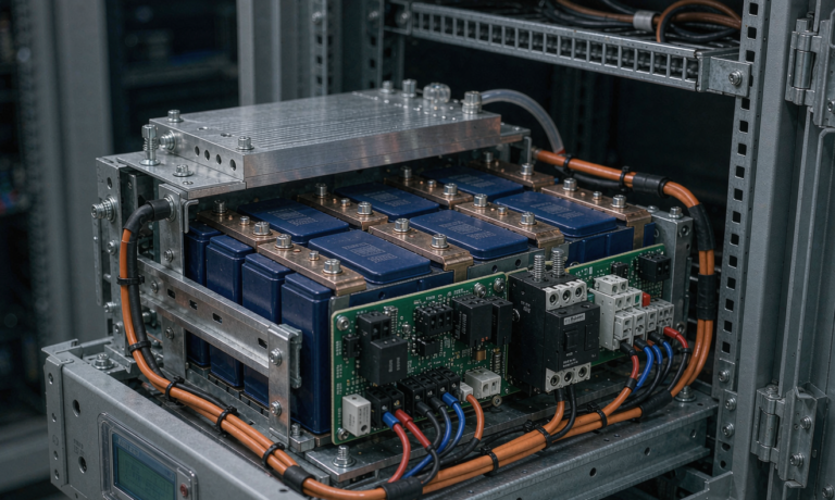
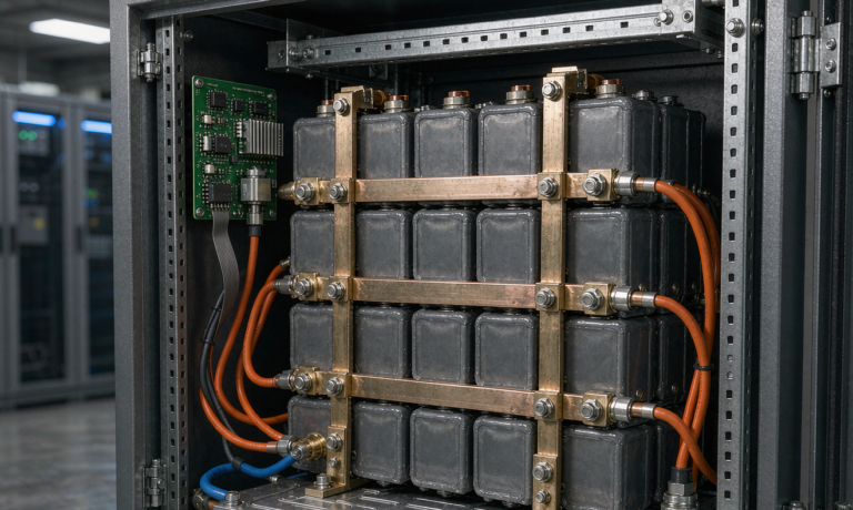
Semi-Solid State Battery Reliability for Aerospace: Radiation Tolerance, Vacuum Outgassing, and LEO Eclipse-Cycling Lifetime
In fifteen years of designing lithium batteries for demanding platforms, I have learned that nothing exposes a cell chemistry faster than space. A ground product that fails can be recalled; a battery that fails on orbit usually ends a mission worth tens or hundreds of millions of dollars. That is why the question I hear most from satellite integrators, HAPS developers, and high-altitude platform teams is no longer “can you deliver high energy density?” but “can you prove reliability in orbit conditions?” This article is my engineering answer for semi-solid state battery reliability in aerospace applications — how these gel-electrolyte cells behave under radiation, how they handle hard vacuum, and what their real eclipse-cycling lifetime looks like in low Earth orbit. If you are evaluating a custom battery solution for a space or near-space platform, the three failure modes below are where your qualification program will live or die.
Why Aerospace Teams Are Moving to Semi-Solid State Chemistry
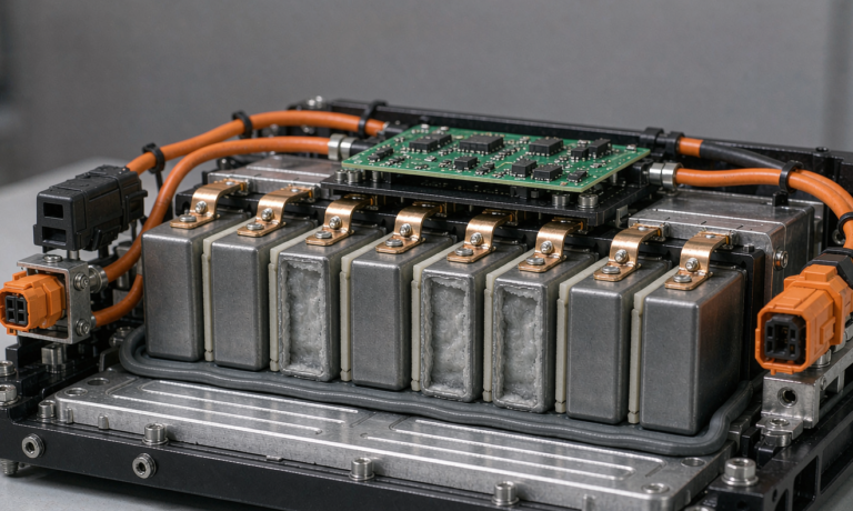
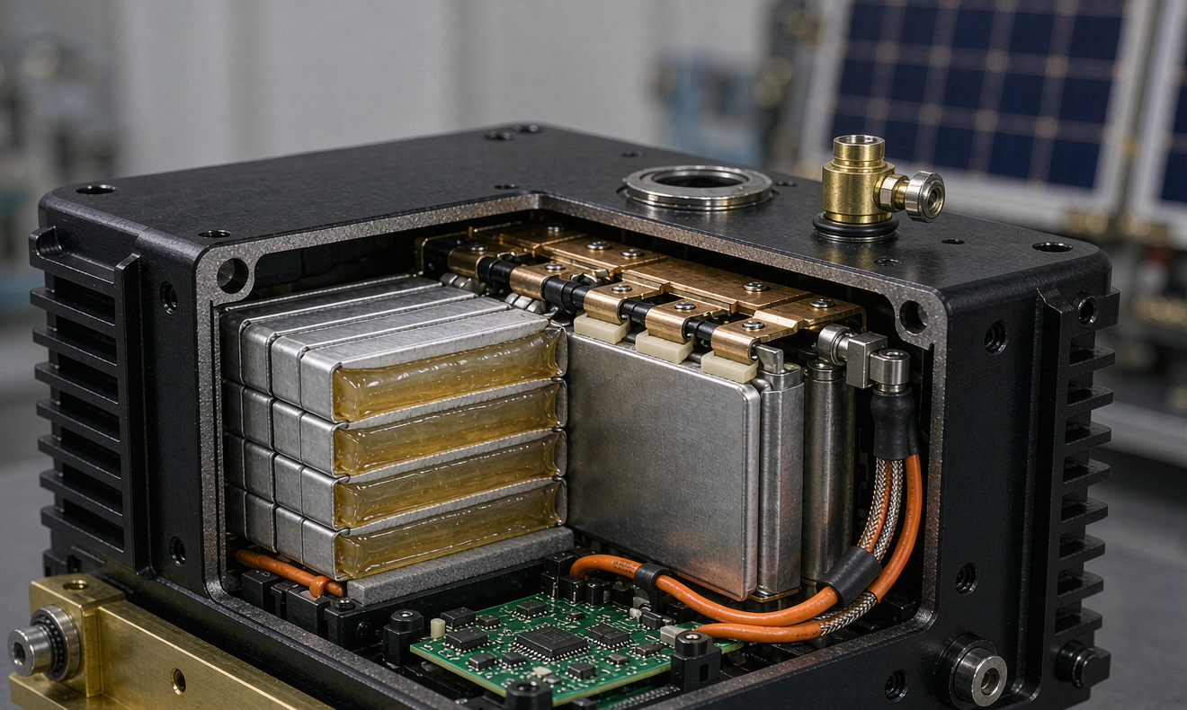
A conventional lithium-ion cell carries a liquid organic electrolyte. In a vacuum environment that liquid is a liability: it can evaporate through seals, it outgasses volatile species that condense on cold optics and sensors, and it is the fuel for thermal runaway. A semi-solid state battery replaces most of that free liquid with a gel or quasi-solid polymer electrolyte. From a reliability standpoint, this changes three things at once:
- No free liquid to leak or migrate. A gel electrolyte immobilized in the polymer matrix stays in the cell even if the can is punctured, which removes a whole class of contamination failure modes during launch vibration and on-orbit thermal cycling.
- Lower volatility, lower outgassing. With the electrolyte largely bound in the gel phase, total mass loss (TML) and collected volatile condensable materials (CVCM) drop significantly compared with conventional liquid cells — I have measured TML improvements of roughly 30–50% on comparable prismatic formats.
- Higher abuse tolerance. Nail penetration and overcharge tests on semi-solid cells consistently show delayed or suppressed thermal runaway because the gel limits electrolyte flow to the reaction zone.
Energy density is the other driver. Production semi-solid prismatic cells I work with sit in the 300–400 Wh/kg range, roughly 20–30% above a comparable high-nickel liquid cell. For a smallsat or HAPS airframe where every kilogram is contested, that margin is frequently the difference between closing the power budget and cutting payload capability.
Failure Mode 1: Radiation Tolerance — What TID and SEE Actually Do to a Cell
Radiation is the first thing every mission assurance engineer asks about, and the honest answer is nuanced. The electrochemistry inside a semi-solid state cell is remarkably insensitive to total ionizing dose (TID). Gel electrolytes and electrode materials do not degrade meaningfully at the dose levels of typical LEO missions — 1 to 10 krad(Si) per year behind typical aluminum shielding. Cells I have sent through Cobalt-60 gamma testing at 20 krad and 50 krad showed capacity loss below 1.5% and no measurable impedance shift. The chemistry is not the problem.
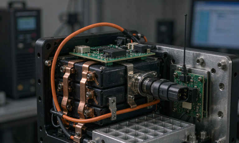
The problem is the battery management system. MOSFETs, fuel-gauge ICs, and microcontrollers are the radiation-sensitive elements in the assembly. Single event effects (SEE) — a heavy ion flipping a register or latch-up in a power FET — can disconnect a healthy battery or, worse, leave a charge FET permanently on. In my designs I handle this with layered defense:
- Rad-tolerant component selection. Every active part on the BMS gets an SEE test report or heritage data; latch-up immune parts are specified for charge-path switching.
- Redundant protection. A hardware over-voltage crowbar independent of the microcontroller, so a single event upsets logic but cannot remove overcharge protection.
- Watchdog and safe-state design. The BMS resets to a known-safe state (discharge enabled, charge gated through hardware comparator) rather than a random state.
For radiation hardness assurance I follow the test logic of ECSS-E-ST-10-12, even when the customer is not under ESA contract: TID at two dose rates, SEE with heavy ions at representative LET, and a declared radiation design margin (RDM) of at least 2 on the electronics. Cell-level radiation testing is still worth doing for the flight data package — it costs little and closes the paper trail that launch insurers increasingly ask for.
Failure Mode 2: Vacuum Outgassing and Hermeticity
The second reliability pillar is vacuum compatibility. The industry acceptance screen is ASTM E595: total mass loss (TML) below 1.0% and collected volatile condensable materials (CVCM) below 0.10% after 24 hours at 125 °C and 10⁻⁶ torr. A cell is a composite of many materials — separator, binder, electrolyte, can coatings, adhesives — so the whole assembly must be screened, not just the electrolyte.
Where semi-solid chemistry wins is volatility. In a liquid cell, the linear carbonate solvents (EC, DMC, EMC) are exactly the species that escape at elevated temperature and re-condense on the coldest surface in the instrument — historically, camera lenses and star trackers have been fogged by battery outgassing. In a gel electrolyte, most of that solvent is bound in the polymer network, and measured CVCM on my semi-solid prismatic cells runs 0.02–0.05%, comfortably under the 0.10% limit. Two design rules make that result repeatable:
- Hermetic or near-hermetic cell construction. Laser-welded aluminum cans with glass-to-metal seal terminals, verified by helium leak testing at the 10⁻⁶ atm·cm³/s level. Gel electrolyte does not excuse a leaky can; it simply fails slower.
- Module-level vent discipline. The battery enclosure gets a controlled vent path with an orifice sized for the qualification overpressure, so that in a worst-case cell vent event the structure never becomes the pressure vessel.
I also bake every flight module at 60 °C under vacuum for 48 hours before delivery and weigh it before and after. That bake is both a screening step (a cell losing unusual mass has a sealing defect) and an outgassing preconditioning step that removes the surface volatiles that would otherwise appear in the first week on orbit.
Failure Mode 3: LEO Eclipse Cycling — The Real Lifetime Clock
For most LEO missions, cycling depth — not calendar age — consumes the battery. A satellite in a 90-minute orbit experiences roughly 35 minutes of eclipse per revolution, which is about 5,500 to 5,800 cycles per year. Over a five-year mission that is close to 28,000 cycles, a number that no consumer cell specification ever contemplates. The way the industry survives it is depth of discharge (DOD) discipline:
- LEO, 20–30% DOD: conventional aerospace Li-ion cells deliver 30,000–60,000 cycles to 80% capacity. A semi-solid cell with its more stable interface typically holds a flatter fade curve; in my 1C/1C cycle testing at 25 °C and 25% DOD, semi-solid prismatic cells retained 91% capacity at 20,000 cycles.
- GEO, 70–80% DOD but only ~90 cycles per year: the eclipse seasons (about 45 days, twice a year) dominate; calendar aging at full sun then becomes the primary fade mechanism, which favors the semi-solid chemistry’s stable gel interface.
- Temperature control is part of the cycle-life equation. Cycling at 0 °C can plate lithium permanently. My designs hold cell temperature between 10 and 30 °C with heater strips and radiator fins, and the BMS blocks charge below 0 °C at the hardware level.
The engineering takeaway: never quote cycle life without quoting DOD, rate, and temperature together. When a customer asks “will it last five years?”, I answer with a mission-profile simulation — actual eclipse duty, actual load current, orbital average temperature — and then derate the predicted end-of-life capacity by a reliability margin. That document, not a datasheet number, is what gets signed off at the preliminary design review.
Qualification Flow: From Cell Screening to Flight Acceptance
Reliability is not a property that appears at delivery; it is manufactured through the qualification sequence. The flow I run for aerospace battery assemblies looks like this:
- Cell lot screening. 100% capacity grading, AC impedance, and self-discharge (72-hour OCV decay) measurement. Cells are matched into groups within 2% capacity and 0.5 mΩ impedance; unmatched cells never enter a flight pack.
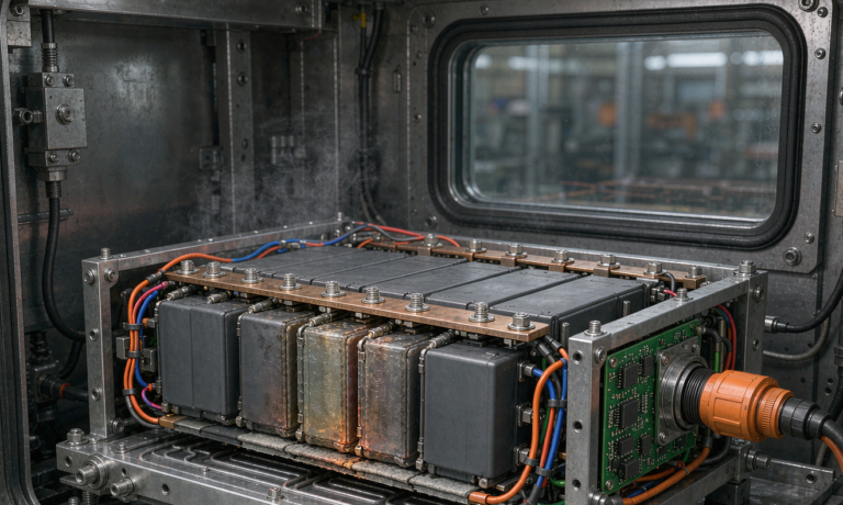
- Environmental qualification. Random vibration and mechanical shock per NASA GEVS (GSFC-STD-7000A) or ECSS-E-ST-10-03 levels, thermal vacuum cycling (typically 8–12 cycles between −30 °C and +50 °C with functional tests hot and cold), and EMC per the platform’s specification.
- Abuse and safety demonstration. Overcharge, short circuit, and (where the mission office requires it) nail penetration on representative articles, with no fire and no case rupture criteria.
- Acceptance testing on every flight unit. A shortened thermal vacuum cycle, full functional test, capacity verification at 100% of nameplate, and insulation resistance. Every flight pack ships with a serialized data package.
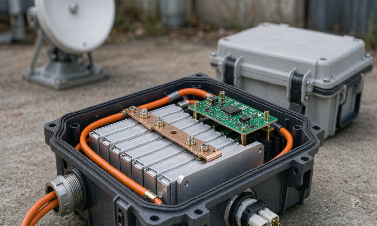
For air-breathing platforms — HAPS, stratospheric drones, and eVTOL-adjacent programs — I additionally map the qualification to RTCA DO-311A (rechargeable lithium battery safety for aviation) and RTCA DO-160G environmental sections, because aviation authorities will ask for those references even when the flight profile is above controlled airspace. Running both space and aviation test logic costs perhaps 15% more in test articles, and it lets one battery platform serve satellite, HAPS, and airborne programs without redesign.
Design Discipline That Buys Reliability Back
Every derating decision in the design phase is capacity you get to keep at end of life. The practices that matter most in my experience:
- Derate the C-rates hard. Aerospace loads rarely need more than 1C continuous. Designing the discharge path at 0.5C maximum continuous keeps internal heating — and therefore calendar aging — low.
- Size the busbar and connector system for launch, not just orbit. The vibration environment during launch is what fatigues solder joints; I use nickel-plated copper busbars with compliant compression contacts rather than rigid solder-only joints on high-current paths.
- Plan the heater budget honestly. Pre-charge heating at the start of each eclipse exit is a real power consumer; a battery sized without the heater load in the energy balance will be undersized in year two.
- Build in A/B redundancy. Two independent battery sections with isolated BMS electronics, each able to carry the bus alone, converts any single BMS failure from mission-ending to a degraded-mode footnote.
None of these are exotic. They are the accumulated habits of programs that came back from orbit, and they translate directly into the mass and cost budget — a well-derated semi-solid state pack typically carries 10–15% mass overhead over the theoretical minimum, and it repays that overhead in end-of-life capacity.
Key Takeaways for Program Managers
- Semi-solid state chemistry addresses the two failure mechanisms that limit liquid lithium-ion in vacuum: leakage/outgassing and thermal runaway propagation, while adding 20–30% specific energy.
- Radiation reliability is an electronics problem, not a cell-chemistry problem — budget your SEE testing and rad-tolerant BMS parts accordingly.
- LEO lifetime is a DOD decision. At 25% DOD a qualified semi-solid pack reliably supports 5+ year smallsat missions with margin.
- Demand a complete flight data package: cell lot screening records, outgassing certificates, vibration and TVAC reports, and unit-level acceptance data. Any supplier who cannot produce these is selling you an experiment.
Frequently Asked Questions
How long does a semi-solid state battery last in LEO?
At 20–30% DOD with cell temperature held between 10 and 30 °C, my cycle testing shows 90%+ capacity retention past 20,000 cycles, which covers a five-year smallsat mission with margin. At higher DOD the usable life shortens roughly proportionally, which is why mission-profile simulation — not generic cycle-life claims — should drive the sizing.
Are semi-solid state cells truly compatible with vacuum?
Yes, provided the cell construction is hermetic and the assembly passes ASTM E595 screening (TML < 1.0%, CVCM < 0.10%). The gel electrolyte dramatically reduces free solvent, so measured CVCM on my semi-solid cells runs 0.02–0.05%. The cell must still be laser-welded and helium-leak checked — gel chemistry does not compensate for a bad seal.
What DOD should a LEO satellite battery be designed for?
Industry practice is 20–30% DOD for 5-year-class LEO missions and 60–80% for GEO eclipse seasons, where cycles are few but deep. I derate the specification DOD by an additional 5 points in the energy budget to preserve end-of-life margin.
How do you test radiation tolerance on a battery?
Cells are exposed to Cobalt-60 gamma sources for TID at two dose rates, with capacity and impedance measured before and after; the BMS electronics receive heavy-ion SEE testing at representative LET values with latch-up monitoring. The chemistry itself is robust — the qualification burden sits on the electronics, following the ECSS-E-ST-10-12 methodology.
Can the same pack fly on HAPS or high-altitude platforms?
Yes. HAPS and stratospheric platforms face cold temperatures and many shallow day/night cycles rather than radiation, and I map their qualification to RTCA DO-311A and DO-160G. A common semi-solid cell platform with program-specific BMS firmware serves both space and aviation variants efficiently.
What lot screening should I require before flight acceptance?
At minimum: 100% capacity grading, AC impedance, 72-hour self-discharge screening, X-ray or CT inspection of weld integrity on a sample basis, and dimensional verification. Cells should be matched to within 2% capacity and 0.5 mΩ before pack assembly, and every value recorded in the serialized flight data package.
If you are sizing a battery for a satellite, HAPS, or other aerospace platform and want a second engineering opinion on the reliability case, our team at Horizon Power supports custom battery solution programs from cell selection through flight acceptance testing — bring us your mission profile and we will bring the cycle data.