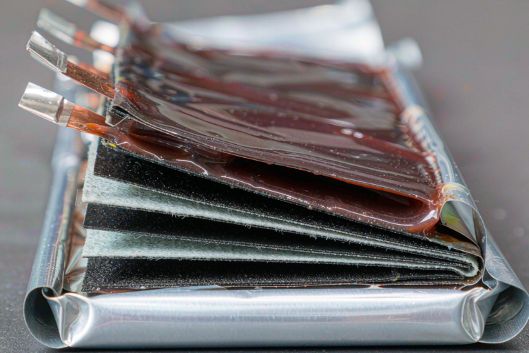
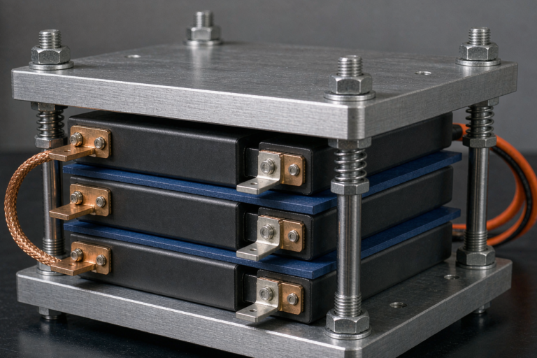
Semi-Solid State Battery Separator and Interface Engineering
Why the Separator and Interface Decide Semi-Solid Performance
When engineers talk about semi-solid state batteries, most of the marketing attention goes to energy density and range. In my daily work as a senior lithium battery engineer, the real battle is fought at the micrometer scale — at the separator and at the interface between the electrodes and the semi-solid electrolyte. Get those two right and you get high ionic conductivity, long cycle life, and a cell that stays safe under abuse. Get them wrong and you spend months chasing lithium dendrites, pouch swelling, and sudden impedance growth that no amount of BMS tuning can fix.
A semi-solid state battery is not a pure solid-state cell. It uses a gel or slurry-like electrolyte that is partly liquid, partly solid — typically 5% to 15% retained solvent by weight. That small amount of liquid gives you the wetting and ionic transport behavior that makes manufacturing practical today, while removing most of the flammable free electrolyte that makes a conventional lithium battery risky. But it also means the separator and the electrode–electrolyte interface carry far more responsibility than they do in a liquid cell.
I like to tell new team members that in a semi-solid design the separator is not a passive membrane. It is an active part of the ion pathway, and the interface is where the cell either earns its cycle life or loses it.
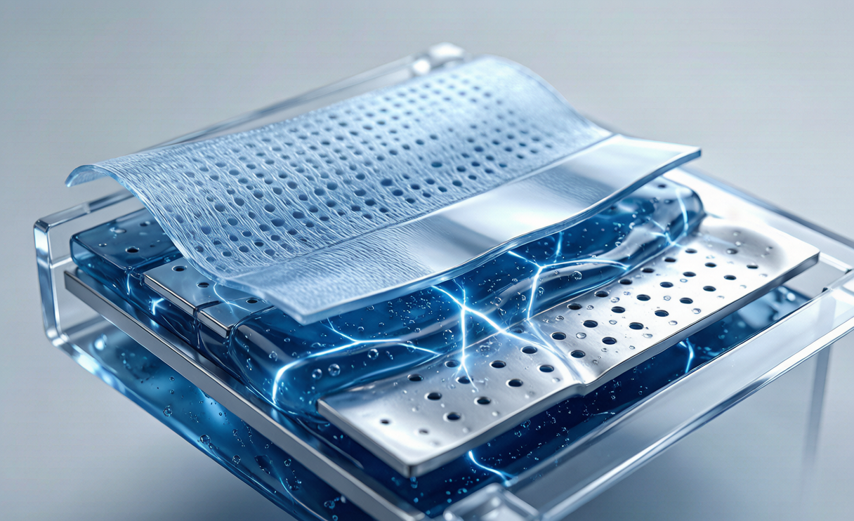
Separators That Work in a Semi-Solid System
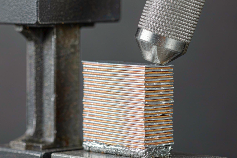
The default choice on our pilot lines is a ceramic-coated polyethylene (PE) separator. We typically run a 12–16 µm base film with a 2–4 µm alumina (Al₂O₃) or silica coating on one or both sides. The ceramic coating raises the shutdown temperature and suppresses thermal shrinkage, which matters a great deal when you have removed most of the liquid electrolyte and can no longer rely on it for heat absorption.
- Base film thickness: 12–16 µm keeps area-specific resistance low while preserving mechanical strength during stacking and winding.
- Porosity: 40–50% balances electrolyte uptake against puncture resistance.
- Gurley value: 200–400 s/100cc, tuned so the semi-solid electrolyte can wet the pores without bleeding through under high stack compression.
- Coating chemistry: Al₂O₃ for thermal stability; PVDF or aramid blends for adhesion to the semi-solid layer.
In a custom battery solution where the pack must survive vibration, rapid altitude changes, and mechanical shock, we sometimes move to a non-woven composite or aramid-backed separator. It costs more per square meter but tolerates the flexing that drone and aerospace packs see on every flight, and it resists the micro-folding that seeds soft shorts.
Engineering the Electrode–Electrolyte Interface
The interface is where the semi-solid electrolyte meets the cathode and the anode. Two interphases dominate the cell: the solid electrolyte interphase (SEI) on the negative electrode and the cathode electrolyte interphase (CEI) on the positive electrode. In a semi-solid system, both films must be thin, ionically conductive, and electronically insulating — and they must stay that way for hundreds of cycles.
We build the SEI during a controlled formation cycle at 0.05C–0.1C, holding the cell inside a narrow voltage window so the electrolyte additive package — often a small dose of lithium bis(fluorosulfonyl)imide, LiFSI, plus a film-forming ester — grows a stable, fluoride-rich layer. If formation is rushed to save time, you get a thick, resistive SEI that never recovers, and the cell spends its whole life fighting interfacial impedance it should never have had.
The CEI is the harder problem because high-nickel cathodes such as NMC811 or NCMA are chemically aggressive toward the electrolyte. We protect them with a thin coating of lithium niobate or lithium phosphate and keep the semi-solid electrolyte slightly lithium-rich near the cathode. This quiet detail is one of the real reasons a well-engineered semi-solid state battery outlasts a poorly engineered one by a factor of two or three in cycle life.
Anode choice also shapes the interface. We run graphite at the conservative end and silicon-blended anodes (5%–15% Si) where energy density is the priority. Silicon swells on lithiation, so the SEI must be compliant enough to flex without cracking — another reason the separator and interface must be designed together, not separately.
Ionic Conductivity and Interfacial Impedance Targets
For a semi-solid electrolyte to compete with liquid cells, bulk ionic conductivity should sit around 0.8–1.5 mS/cm at 25 °C. Below that band, the cell needs to run warm, which defeats the purpose and complicates thermal management. We measure conductivity with electrochemical impedance spectroscopy (EIS) on a symmetric cell, then deconvolute the bulk, grain-boundary, and interfacial contributions so we know exactly which layer is limiting performance.
The number we watch most closely is interfacial impedance. A healthy semi-solid interface should land below roughly 30 Ω·cm² after formation. If it climbs above 50 Ω·cm² within the first 50 cycles, something in the interphase is breaking down — usually CEI dissolution, anode side reactions with trace water, or lithium plating at the edge of the electrode.
- Bulk conductivity: 0.8–1.5 mS/cm at 25 °C.
- Interfacial impedance: target below 30 Ω·cm² post-formation.
- Cycle life: 800–1,200 cycles to 80% state of health at 1C for well-engineered cells.
- Energy density: 300–400 Wh/kg at the pack level, depending on form factor and cooling.
Manufacturing and Quality Control at Scale
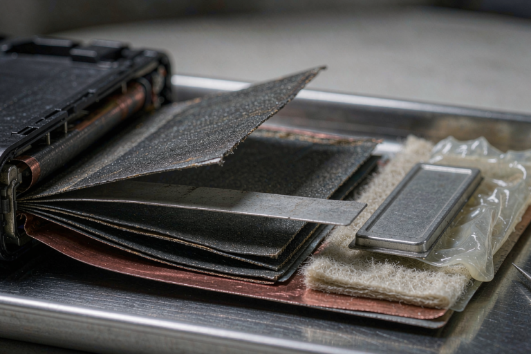
Lab results mean nothing if you cannot repeat them on the line. On our pilot production, separator handling is the step most likely to introduce defects: a single fold, fiber, or metallic particle on the separator becomes a soft short after stacking. We run 100% optical inspection and a laser-based thickness map of every separator roll before it reaches the coater.
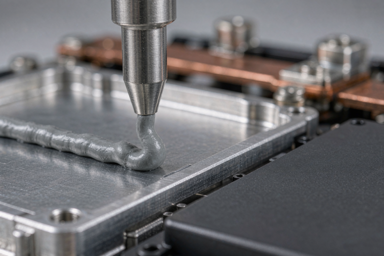
The semi-solid electrolyte is coated as a slurry with a comma-bar or slot-die coater at 20–60 µm wet, then partially dried so it retains just enough solvent to stay ionically active but not so much that it flows under compression. We hold the dry room below 20 ppm water and below 5 ppm oxygen during electrode stacking, because trace moisture is the enemy of a clean SEI and the cause of most gas generation during formation.
For any volume custom battery solution, we lock the interface recipe with a design-of-experiments (DOE) matrix and then freeze it. Changing the cathode coating, the silicon content, or the separator supplier without re-qualifying the interface is the fastest route to shipping a cell that looks fine in the lab and fails in the field. Calendering pressure is logged per lot, because over-compression closes the separator pores and quietly kills ionic conductivity.
Safety, Standards, and What We Validate
A semi-solid state battery is safer than a liquid lithium battery because there is far less free flammable electrolyte, but it is not exempt from certification. Every cell we release passes the full UN38.3 transportation test suite — altitude simulation, thermal test, vibration, shock, external short circuit, impact, and forced discharge. For consumer and industrial packs we also validate against IEC 62133 for cell and pack safety, and for aviation-bound products we design within FAA and EASA guidance on lithium battery carriage, thermal runaway containment, and propagation limits.
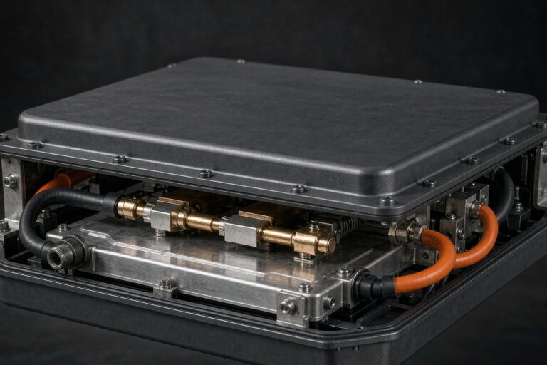
We specifically test interface stability under abuse: nail penetration, overcharge to 1.5× rated voltage, and external short at elevated temperature. The objective is not merely to pass once but to prove the separator and interphase fail gracefully — limiting heat propagation to neighboring cells rather than feeding it. In pack validation we run a thermal propagation test aligned with electric-vehicle battery safety thinking, because a B2B customer cares about the whole pack, not just a single glowing cell.
Frequently Asked Questions
What is the difference between a semi-solid state battery and a solid-state battery?
A solid-state cell uses a fully solid electrolyte with no free liquid. A semi-solid state battery keeps a gel or slurry electrolyte, which makes manufacturing and interfacial contact far easier at the cost of some energy density and a small amount of retained solvent. For most B2B applications today, semi-solid is the practical bridge technology that can actually be built at scale.
Why does the separator still matter if the electrolyte is mostly solid?
Because the separator physically separates the electrodes and defines the interface. Even in a semi-solid cell, a weak or poorly coated separator lets dendrites bridge and impedance climb. The separator and the semi-solid electrolyte function as one system, and designing them separately is a mistake we see too often.
How do you measure interfacial impedance in production?
We use electrochemical impedance spectroscopy on formation-aged cells and track the high-frequency intercept and the semicircle growth over cycle count. A rise beyond our threshold triggers a quarantine and a recipe review before the cell is ever built into a pack.
Can a semi-solid state battery use the same separators as a conventional lithium battery?
Often yes, especially ceramic-coated PE, but the coating weight and porosity are re-tuned for lower liquid uptake and higher compression tolerance. A direct swap without re-qualifying the interface usually degrades cycle life and can hide a dendrite risk.
Which standards apply to shipping and using these cells?
UN38.3 is mandatory for transport. Depending on the application, IEC 62133 covers cell and pack safety, while FAA and EASA provide the aviation-specific framework. We build the test plan around the destination market and the exact use case rather than a generic checklist.