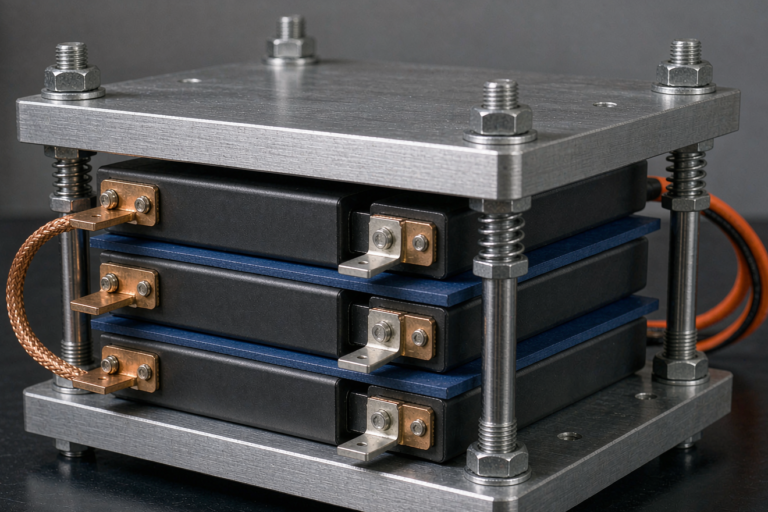
Semi-Solid State Battery Electrode Design: Cathode and Anode Engineering for Real Production
When engineers ask me how to make a better semi-solid state battery, my first answer is almost never about the electrolyte chemistry alone. After fifteen years on the factory floor and in the cell lab, I have learned that semi-solid state battery electrode design is where the real performance battle is won or lost. The cathode and anode are not passive sheets that simply hold active material — they are engineered architectures that decide energy density, power, cycle life, and safety. At Horizon Power we treat electrode design as a system problem, because that is what it is.
Why Electrode Design Defines Semi-Solid State Cell Performance
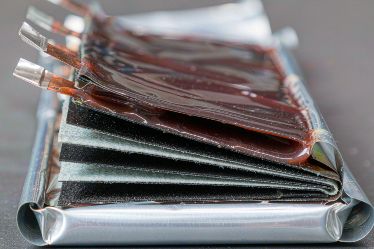
A semi-solid state cell sits between a conventional lithium battery with a liquid electrolyte and a fully solid-state cell with a rigid ceramic separator. We use a semi-solid electrolyte — typically a gel polymer or a suspension of oxide or sulfide particles in an ionic liquid — that stays soft enough to wet the electrodes yet conductive enough to move lithium ions at useful rates. The beauty of this approach is that it tolerates conventional electrode manufacturing far better than fully solid systems, but it also means the electrode itself must be designed around the semi-solid interface.
In my experience the three numbers that matter most out of the gate are ionic conductivity at the interface (we target 1 to 10 mS/cm in the wet electrode layer), areal loading (mg/cm² of active material), and the electrode porosity that the semi-solid electrolyte must fill. Get those wrong and no amount of cathode chemistry will save the cell. A drone battery pack, for example, lives or dies on the power density you can pull from a thick, low-porosity electrode without the voltage collapsing under load.
Cathode Engineering — Materials, Loading, and Architecture
For most of our semi-solid state battery programs the cathode is nickel-rich layered oxide — NMC811 or NCA — because the energy density target simply demands a high specific capacity cathode. We have also shipped LFP cathodes where cycle life and thermal forgiveness outrank raw energy, such as home energy storage and industrial packs that sit at partial state of charge for years.
- Active material choice: NMC811 gives us roughly 200 mAh/g, while LFP sits near 160 mAh/g but with a flatter voltage curve and superior calendar life. The choice is a system trade, not a material preference.
- Areal loading: We routinely coat 18 to 28 mg/cm² on the cathode. Going thick raises energy per area but lengthens the lithium-ion diffusion path, so the semi-solid electrolyte must compensate with higher local conductivity.
- Conductive network: A carbon black and CNT blend forms the electron highway. Too little and the electrode is electronically dead; too much and you dilute active material and hurt energy density.
- Binder and porosity: We tune PVDF or a water-based binder so the final calendered electrode leaves 25 to 35 percent porosity for the semi-solid electrolyte to infiltrate. This is the single most iterated parameter in our pilot line.
The cathode-electrolyte interphase, or CEI, is where a lot of semi-solid cells fail prematurely. A poorly stabilized cathode surface reacts with the electrolyte, grows impedance, and the cell loses capacity in the first hundred cycles. We stabilize the surface with a thin coating — alumina or lithium phosphate based — and validate it under accelerated aging before any design reaches production.
Anode Engineering — From Graphite to Silicon and Lithium Metal
The anode is where semi-solid state chemistry gets interesting. The simplest, most reliable path is a graphite or silicon-graphite composite anode, and that is what we ship in the majority of our custom battery solution programs today because it is manufacturable and safe.
Graphite anodes are mature: we control the particle size distribution and the conductive additive so the semi-solid electrolyte wets evenly and lithium plates uniformly during fast charge. The risk with graphite is lithium plating at high C-rate, so we constrain the charge window and add a small silicon fraction — typically 5 to 10 percent Si — to lift capacity without cracking the electrode.
For higher energy programs we are now qualifying silicon-dominant anodes up to 50 percent silicon. Silicon swells roughly 300 percent on lithiation, so the electrode must be engineered with an elastic binder and a porous host structure that accommodates volume change. This is exactly the kind of design work that separates a lab curiosity from a cell that survives 800 cycles in the field.
Looking further out, lithium-metal anodes paired with a protective interlayer are the holy grail for semi-solid state battery electrode design, because metallic lithium roughly triples anode capacity versus graphite. We run lithium-metal anodes in our R&D fleet with a ceramic or polymer protective layer that suppresses dendrite growth. It is not yet our default production choice, but the data is moving in the right direction.
The Semi-Solid Electrolyte and the Electrode Interface
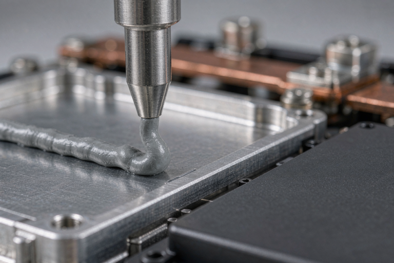
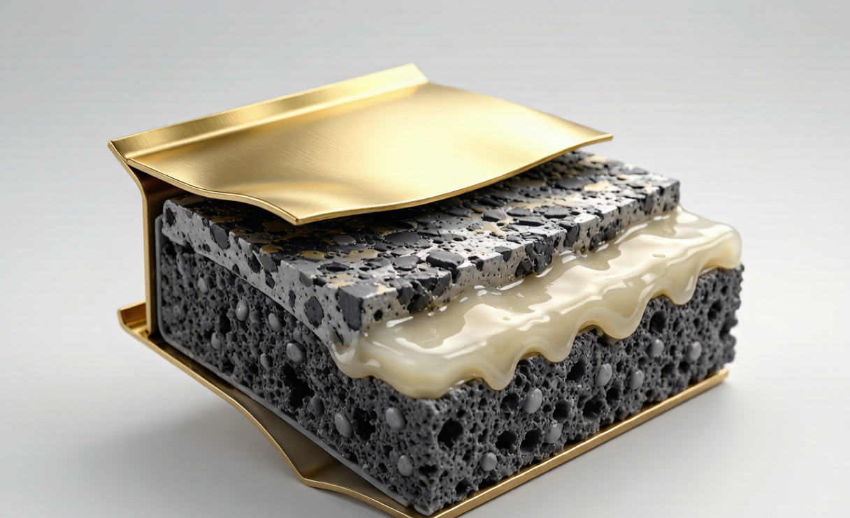
A lithium battery is only as good as the interface where the solid electrode meets the ion-conducting medium. In a semi-solid cell the electrode is coated, then the semi-solid electrolyte is either coated on top or infused into the porous structure. The goal is intimate contact with no dry spots, because a dry spot is a high-impedance island that ages faster than its neighbors.
We characterize the interface with electrochemical impedance spectroscopy and track the growth of the SEI and CEI films over hundreds of cycles. When a cell from our line shows a rising interfacial resistance, nine times out of ten the root cause traces back to electrode surface treatment, not the bulk electrolyte. That is why semi-solid state battery electrode design and interface engineering are really the same discipline.
Manufacturing the Electrodes at Scale
Design that cannot be manufactured is just a slide deck. Our semi-solid electrodes are made with the same coating and calendering assets used for conventional lithium-ion, which is the whole commercial point of the semi-solid route.
- Slurry coating: We meter a precisely controlled slurry through a doctor blade onto a copper or aluminum current collector at line speeds tuned to avoid striations.
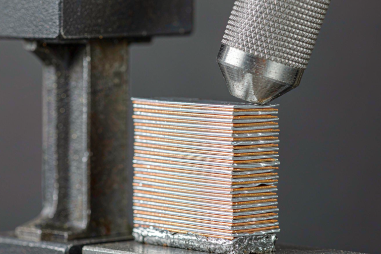
- Calendering: Roll pressure compacts the electrode to target porosity. Over-calender and you crack the conductive network; under-calender and the semi-solid electrolyte cannot bridge the gaps.
- Dry electrode option: For some programs we use a PTFE-fibrillated dry process that eliminates solvent drying, reduces energy per square meter, and improves electrode density. It is more demanding on equipment but attractive for high-volume custom battery solution runs.
Every coil is sampled for loading uniformity, thickness, and adhesion before it enters cell assembly. I personally review the first-article report on any new electrode design, because a 2 micrometer thickness drift across the web becomes a measurable capacity spread across the finished pack.
How We Validate Electrode Designs — Standards and Field Data
An electrode design is not released on a good lab curve. We qualify against the standards our customers’ end products must pass. For transport, cells comply with UN38.3 (the T.1 through T.8 sequence: altitude, thermal, vibration, shock, external short, impact, overcharge, and forced discharge). For product safety we build to IEC 62133-2 and IEC 62619 for industrial and stationary applications, with UL 1973 and UL 1642 referenced where the market requires.
For aviation and long-range drone battery programs, we design and document to the expectations of FAA and EASA certification paths, because a cell that behaves perfectly on the bench but fails a thermal runaway propagation test will never fly. We run nail penetration, external short, and overcharge to destruction, then feed the failure modes back into the next electrode iteration. That loop — design, abuse test, redesign — is what earns the trust of B2B buyers who cannot afford a field recall.
Design Tradeoffs for Drone, Storage, and Industrial Packs
The same electrode design never serves every application, and pretending otherwise is how teams waste a year. For a drone battery we push cathode loading and silicon content to maximize Wh/kg, accept a shorter cycle life, and engineer the thermal path so a hard landing does not become a thermal event. For home energy storage we flip the priority: LFP chemistry, conservative loading, and a benign CEI so the pack is still healthy after ten years of daily cycling.
Industrial and motive packs — forklifts, cleaning equipment, two-wheelers — sit in the middle. They want high cycle life and fast charge, so we tune porosity and the conductive network for sustained power rather than peak energy. Every one of these is delivered as a custom battery solution because the electrode recipe, the tab design, and the module arrangement are all entangled.
Frequently Asked Questions
What is the most important parameter in semi-solid state battery electrode design?
In practice it is the porosity and wetting the semi-solid electrolyte achieves in the electrode. Ionic conductivity at the interface drives rate capability and cycle life more than the headline cathode chemistry does, especially once you are past the first design iteration.
Can semi-solid state electrodes use existing lithium-ion manufacturing lines?
Yes, and that is the central commercial advantage. We coat, calender, and assemble semi-solid electrodes on assets adapted from conventional lithium battery production, which keeps capital cost and scale-up risk far lower than a fully solid-state route requires.
Which anode works best for a drone battery built on semi-solid chemistry?
For production today we use graphite or a silicon-graphite composite (5 to 10 percent silicon) for the right balance of energy and cycle life. Lithium-metal anodes are in our R&D fleet and offer the highest energy, but they are not yet our default for fielded aviation packs.
How do you ensure a semi-solid electrode design is safe and certifiable?
We qualify to UN38.3 for transport, IEC 62133-2 and IEC 62619 for product safety, and design toward FAA and EASA expectations for aviation use. Abuse testing — nail, short, overcharge — is built into every release gate, not left for the customer to discover.
Why choose a semi-solid state battery over a conventional lithium battery?
A semi-solid state battery typically offers higher energy density and better thermal stability than a liquid-electrolyte lithium battery, while still being manufacturable on proven lines. That combination is why we see strong pull from drone, storage, and industrial customers who need more energy without a fragile, exotic supply chain.