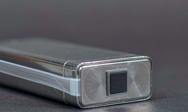
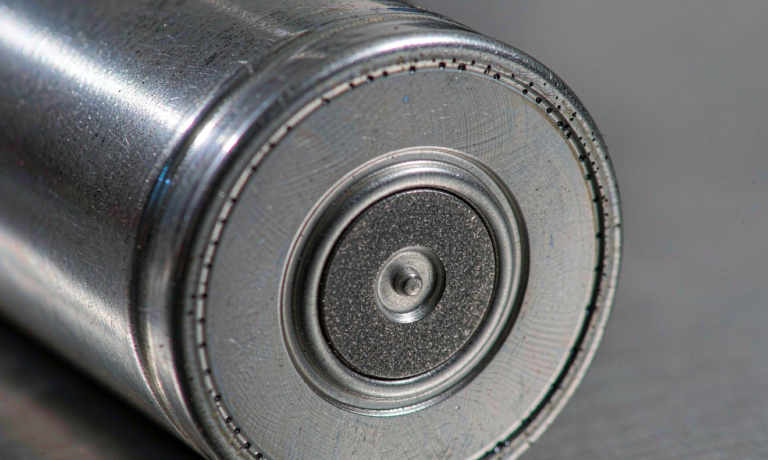
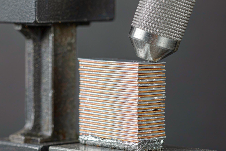
Semi-Solid State Battery BMS Requirements and Tuning
Why Semi-Solid Electrolytes Change the BMS Game
When I first started tuning battery management systems a decade ago, everything I touched was a conventional liquid-electrolyte lithium-ion cell. The rules were well understood: watch voltage, watch temperature, balance the cells, call it a day. Then around 2019 our pilot line began shipping semi-solid state battery packs, and I quickly learned that the BMS playbook I had memorized no longer fully applied. A semi-solid cell sits in a strange, useful middle ground between a classic lithium battery and a true solid-state cell. It keeps a small amount of liquid wetting agent but replaces most of the flammable solvent with a gel-like or polymer-rich electrolyte. That single design choice shifts the entire electrical and thermal fingerprint the BMS has to track.
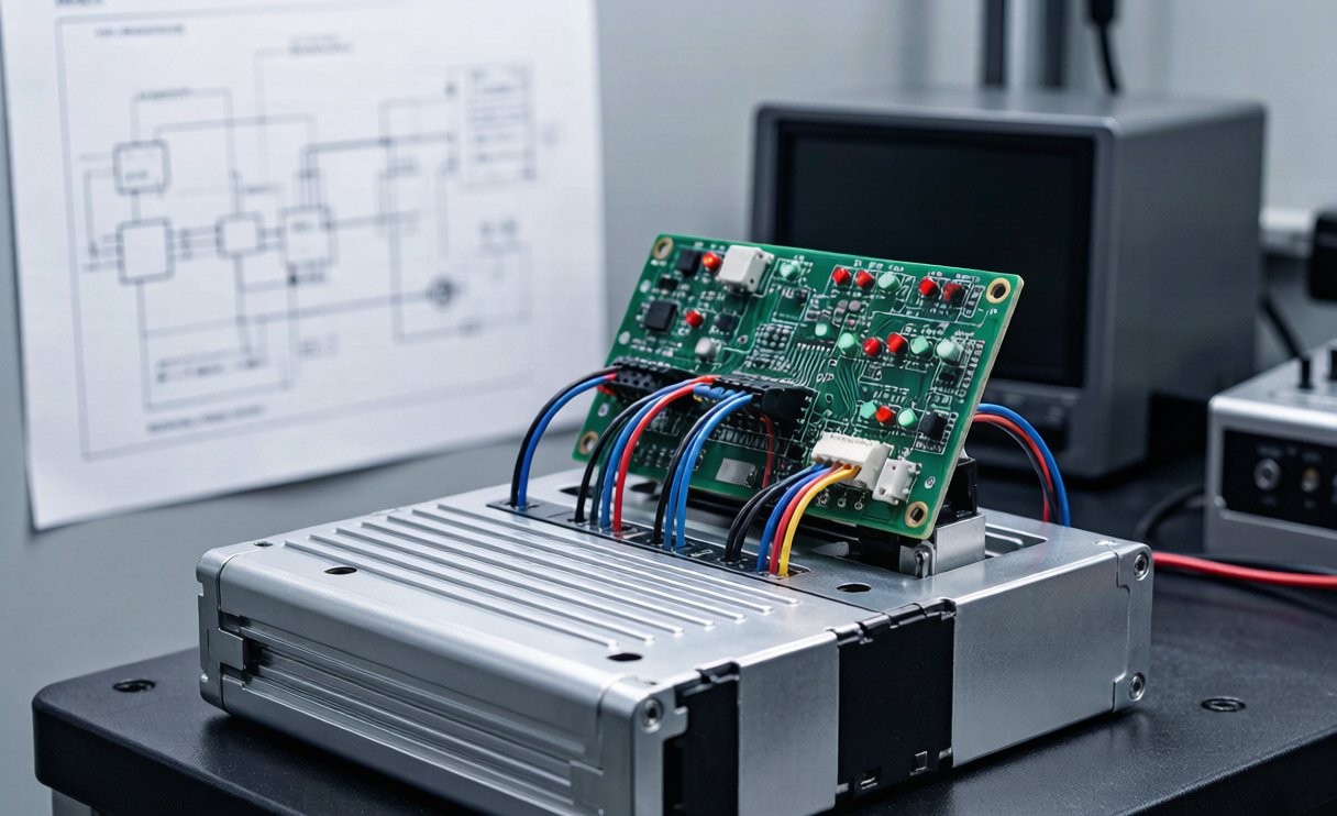
In my lab, the first thing I noticed was narrower operating windows. Semi-solid chemistries tend to tolerate a tighter voltage band before plating or dendrite risk climbs. The second thing was the thermal response. Because the electrolyte is partly solid, heat does not spread the same way it does in a flooded cell, so my old temperature-compensation curves were wrong by a meaningful margin. If you are building a custom battery solution around semi-solid cells, your BMS requirements and tuning strategy have to be re-derived from the cell’s actual behavior, not copied from a datasheet meant for NMC pouch cells.
Core BMS Requirements for Semi-Solid State Batteries
Before we talk about tuning, let’s lock down the non-negotiable semi-solid state battery BMS requirements. These are the baseline specs I hand to every firmware team I work with.
- High-resolution voltage sensing. I specify at least 16-bit ADC per cell, or a 14-bit differential front end with oversampling. Semi-solid cells reward tight window control, so a 1 mV resolution is my floor, not my target.
- Per-cell balancing with adaptive thresholds. Passive balancing is acceptable below 10 A·h, but above that I push for active balancing to avoid wasting the very energy density we paid for.
- Multi-point thermal sensing. At minimum one sensor per module and one near the busbar. Semi-solid packs develop local hot spots differently than liquid cells, so relying on a single pack-level thermistor is asking for trouble.
- SOH and impedance tracking. The BMS must track internal resistance drift, because semi-solid interfaces age in ways liquid cells do not. A resistance jump is often the first sign of interfacial degradation.
- Robust isolation monitoring. With higher pack voltages common in semi-solid designs, I require a 500 V+ isolation resistance check per the relevant safety norms.
None of this is exotic, but the thresholds are different. The same BMS that works fine on an LFP pack will over- or under-protect a semi-solid pack if you ship it with default limits.
Voltage Sensing and Cell Balancing Tuning
Voltage sensing is where most of my tuning time goes. A semi-solid state battery usually rides a slightly higher open-circuit voltage than its liquid cousin at the same state of charge, and the slope near the top of charge is steeper. That means my upper cutoff has to be moved carefully, often by 20 to 50 mV, and the constant-voltage soak window lengthened so the BMS does not trip early and leave capacity on the table.
For balancing, I tune the trigger threshold based on measured cell-to-cell variation after formation. In a recent 24-cell semi-solid module, the spread at ship was about 8 mV. I set passive balancing to engage above a 5 mV delta and tuned the balance current to 80 mA. The result was a pack that stayed within 3 mV across a full season of cycling. Active balancing I reserve for high-capacity packs where the energy lost to passive bleed would hurt the customer’s runtime.
One hard lesson: do not balance against the average cell. Balance toward the lowest healthy cell. If you chase the average, you can silently over-discharge a weak cell during a balancing event, and that is exactly how you accelerate the failure you were trying to prevent.
Thermal Management and SOC/SOH Estimation
Thermal tuning is the second big lever. Semi-solid cells run cooler at the electrode surface but can hide localized heating at the solid-electrolyte interface. My approach is to build a simple thermal model into the BMS and tune its gain against logged data from the first field units. I start conservative: a derating curve that backs off charge current above 45 °C and above 50 °C opens the contactor. After a few months of real telemetry, I tighten or relax the curve based on what the data actually shows.
State of charge (SOC) estimation is trickier than people expect. Coulomb counting alone drifts on semi-solid cells because the coulombic efficiency is not a flat 99.9% across temperature. I pair coulomb counting with an open-circuit-voltage lookup that is unique to the semi-solid chemistry, and I recalibrate the OCV table during each full charge. For state of health (SOH), I trend the AC impedance at a fixed 1 kHz test frequency every 50 cycles. A 15% rise in interfacial resistance has been a reliable early warning in my fleet data.
When a customer asks for a custom battery solution for cold climates, I also tune the low-temperature charge lockout. Semi-solid cells handle cold better than wet cells, but they still dislike charging below 0 °C without a preheat loop, so the BMS gets a preheat request line wired to the thermal management controller.
Safety Standards: UN38.3, IEC 62133, and Air Transport
No BMS discussion is complete without the compliance shell it lives inside. Every semi-solid pack I ship is built to pass UN38.3, the transport safety test regime covering altitude simulation, thermal, vibration, shock, external short, impact, overcharge, and forced discharge. The BMS must support the overcharge and external-short protections that those tests verify, and I document the trip points in the test report.
For the cell and pack construction itself, IEC 62133 is the baseline I design the protection architecture around. It sets the expectations for containment, venting behavior, and abuse tolerance. My BMS firmware enforces the voltage and temperature ceilings that keep the pack inside the IEC 62133 envelope during normal and abnormal use.
If the pack is destined for drones or portable equipment that flies, the air-transport rules from FAA and EASA come into play. Spare or installed cells above 100 Wh require operator approval, and the BMS must present a clean state for inspection and prevent accidental activation in transit. I make sure the pack has a shipping mode that the BMS latches on command, killing all loads and disabling the contactor until a deliberate wake sequence runs.
The point is simple: the BMS is not just a performance optimizer, it is the enforcement layer for every safety standard your customer’s auditors will ask about. Tune it with that responsibility in mind.
My Real-World Tuning Workflow
After a few dozen semi-solid programs, I settled on a workflow that keeps tuning honest and repeatable. First, I run ten formation cycles while logging raw cell voltage and temperature at 1 Hz. Second, I derive the OCV-SOC table and the usable voltage window from that log, not from the supplier’s generic curve. Third, I set conservative BMS limits and ship a small beta batch. Fourth, I collect field telemetry for 60 to 90 days. Fifth, I tune the derating curves, balance thresholds, and SOH triggers against that real data.
This loop is slower than guessing, but it has saved me from two near-recalls. In one program, the beta telemetry showed a slow resistance creep only above 40 °C. My initial generic curve would have missed it for a year. The tuned BMS now flags that condition at 12% resistance rise instead of 25%, and we catch failing modules before the customer ever sees a runtime drop.
For teams building a custom battery solution on semi-solid cells, my advice is to budget real time for this tuning loop. The cells are excellent, but they will punish a BMS that was tuned for the wrong chemistry. Get the data, tune to the data, and keep the feedback loop open after launch.
FAQ
Can I reuse a BMS designed for liquid lithium-ion cells on a semi-solid state battery?
Technically the hardware can often be reused, but the limits and tuning cannot. The voltage window, balance thresholds, thermal derating, and SOH triggers all need to be re-derived for the semi-solid chemistry. Shipping a liquid-cell profile on a semi-solid pack is the fastest way to leave capacity unused or trip false protections.
What is the most important BMS parameter to tune first?
The usable voltage window and the per-cell voltage sensing resolution. Semi-solid cells live in a tighter band, so getting the upper cutoff and the ADC resolution right pays off across balancing, SOC accuracy, and cycle life. Everything else builds on that foundation.
Do semi-solid state batteries need different safety certifications?
The certification framework is the same, anchored by UN38.3 for transport and IEC 62133 for cell and pack safety, with FAA and EASA rules applying to air transport. What changes is the specific trip behavior the BMS must demonstrate during those tests. The standards are constant; the protection logic has to match the chemistry.
How often should I retune the BMS after launch?
I recommend a first tuning review at 60 to 90 days using field telemetry, then a lighter annual review. The biggest gains come from the first real-world data cycle, when you replace assumed curves with measured ones. After that, SOH trends guide incremental adjustments.
Is active or passive balancing better for semi-solid packs?
For small packs under 10 A·h, passive balancing with a tuned threshold is simple and reliable. For large high-capacity packs, active balancing preserves the energy density advantage that justifies choosing a semi-solid design in the first place. The right answer depends on pack size and the customer’s runtime priorities.