Lithium Battery Design for Power Tools: How Engineers Build
I have spent the better part of twelve years designing cells into packs, and I still tell new engineers on my team the same thing: power tools are the most abusive commercial application a lithium battery will ever see, short of aerospace. A drone pack gets flown by someone who paid for it and treats it carefully. A tool pack gets dropped off scaffolding, left in a truck bed at −10°C overnight, charged at noon in direct sun, and then asked to deliver a 100 A pulse into a seized lug nut. Nothing about that is gentle.
That is why lithium battery design for power tools is a discipline of its own. You are not optimizing for one number; you are balancing peak current capability, voltage sag under load, thermal headroom without active cooling, mechanical survival, and cost, all inside a housing whose exterior dimensions were frozen by the tool platform years before you arrived. Below is how my team actually works through that problem, in the order we work through it, with the numbers and standards we hold ourselves to.
Start With the Tool’s Real Current Profile, Not the Datasheet
The single most common mistake I see in outsourced tool pack projects is designing to a nameplate number. A customer says “18 V, 5 Ah, 40 A” and the vendor picks cells to match. Then the pack shuts down in the field on the third impact-wrench trigger pull.
Before I select a single component, I instrument the actual tool. A current shunt or a Hall-effect probe on the pack terminals, a scope capturing at least 10 kHz, and a real operator doing real work. What comes back is never a flat line:
- Impact wrench / impact driver: repetitive pulses of 60–120 A lasting 30–200 ms, with 100–300 ms recovery gaps. Brutal on DCIR, mild on total energy.
- Circular saw / reciprocating saw: sustained 40–60 A for 5–30 s through a cut. This is the thermal worst case.
- Drill / driver: 15–25 A typical, with stall events that can hit 90 A+ for under a second.
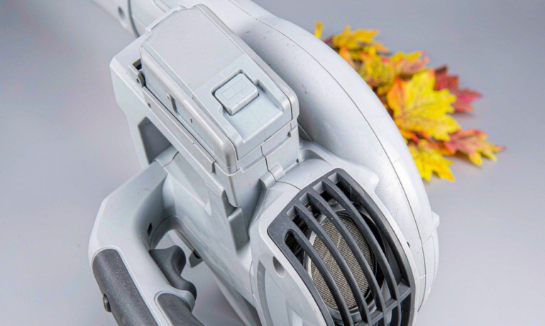
- Blower / vacuum: steady 20–35 A for the entire discharge. This is the cycle-life worst case.
Those four profiles lead to genuinely different packs. I document three numbers from the trace and treat them as contractual design inputs: peak current with duration, sustained current with duration, and total energy per charge under the customer’s duty cycle. Every later decision traces back to those three.
Cell Selection: Where a Power Tool Lithium Battery Is Won or Lost
For tool packs, capacity is a marketing number and DC internal resistance (DCIR) is the engineering number. High-drain and high-energy cells in the same 21700 can differ dramatically:
- High-drain 21700: roughly 3,000–4,000 mAh, 30–45 A continuous rating, DCIR typically 12–18 mΩ.
- High-energy 21700: roughly 4,800–5,000 mAh, 10–15 A continuous, DCIR typically 25–40 mΩ.
The energy cell looks like a 30% runtime win on the spec sheet. Now run the arithmetic that decides whether the tool works. Take a 5S2P pack pulling a 60 A peak, so 30 A per parallel string. With an 15 mΩ high-drain cell, sag is 30 A × 0.015 Ω = 0.45 V per cell, or about 2.25 V across the 5S stack. With a 32 mΩ energy cell, sag is 0.96 V per cell, or roughly 4.8 V across the stack.
Start from a mid-discharge resting voltage near 18.0 V. The high-drain pack sits around 15.7 V under that pulse; the energy pack collapses to roughly 13.2 V. If the tool’s undervoltage lockout is set at 15 V, as many 18 V platforms are, the energy-cell pack simply stops working, and it will do so worst at low state of charge and low temperature where DCIR climbs another 40–80%. That is the whole argument, and it is why I refuse to swap in energy cells on a high-drain platform without re-validating the entire discharge envelope.
Two more rules I hold to. First, specify DCIR at the cold corner, not at 25 C, because −10 C performance generates the warranty claims. Second, match cells for parallel strings within 3–5% on capacity and 10% on DCIR from the same lot; mismatched parallel cells share current unequally and the low-resistance cell ages faster.
Voltage Architecture and Pack Configuration
Tool platforms cluster around a few series counts, and the “max volt” marketing name refers to the fully charged open-circuit voltage rather than the nominal:
- 5S — 18 V nominal, 21 V charged, marketed as 20 V max.
- 10S — 36 V nominal, 42 V charged, marketed as 40 V max.
- 15S — 54 V nominal, 63 V charged, marketed as 60 V max.
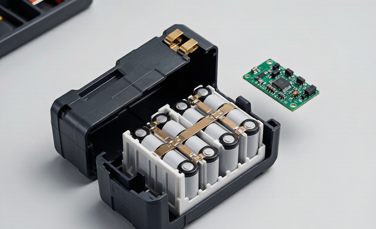
The parallel count is where I spend real design time. A 5S1P pack of five high-drain cells is light and cheap but every cell carries the full pack current, so a 60 A pulse is 60 A per cell, which exceeds most cells’ ratings and drives severe heating. Going 5S2P halves per-cell current to 30 A, halves the I²R heat per cell, roughly doubles capacity, and roughly doubles cycle life at a given pack current, at the cost of weight and bill of materials. For any tool with sustained draw above about 30 A, I default to 2P and argue hard against a 1P cost reduction.
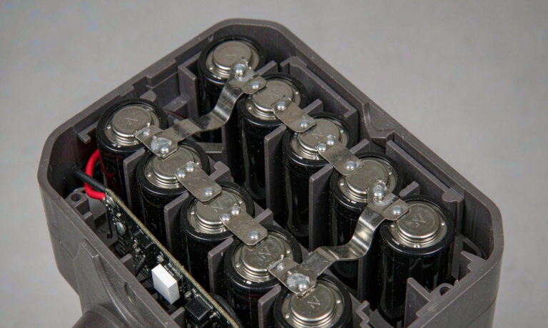
One architecture note that saves warranty pain later: keep the series interconnect path short and wide. In a well-built lithium battery pack, cell DCIR should dominate total pack resistance. If busbars, welds, wiring and terminals contribute more than 15–20%, no cell upgrade will fix the resulting heating problem.
Mechanical Design: The Part That Fails First in the Field
Electrically sound packs still come back from the field, and when they do, the failure is almost always mechanical. Cells are heavy relative to their mounting, and a drop generates enormous transient loads.
My mechanical rules for tool packs:
- Zero cell movement. Cells sit in a molded holder with interference ribs, and I target under 0.1 mm of movement after vibration. Any free play becomes a fatigue crack in a weld or tab.
- Weld for the current, then for the abuse. Pure nickel strip 0.15–0.2 mm thick is standard for 30 A-per-string designs. Resistance spot welding is adequate; laser welding gives lower and more consistent joint resistance where thermal budget is tight. Every joint gets a destructive pull test, and I want more than 20 N per tab with the failure occurring in the nickel, not at the weld nugget.
- Strain relief everything. Sense wires are the number one field failure I see in competitor teardowns. They get routed, retained, and given a service loop, never pulled taut across a cell edge.
- Housing material chosen for impact, not gloss. Glass-filled nylon or PC/ABS blends, with ribbed corners, because real drops land on corners.
- Design to jobsite reality. IEC 62133-2 uses a 1 m drop; I validate at 2 m onto concrete across all six faces and four corners, because that is what a pack falling from a ladder actually experiences.
Thermal Design With No Fan and No Coolant
A tool pack is passively cooled inside a sealed plastic box, which means all the heat you generate must be absorbed by thermal mass during the cut and then shed between cuts. The math is unforgiving. In a 5S2P pack at a sustained 40 A, each cell carries 20 A, so per-cell dissipation is 20² × 0.015 = 6 W, and ten cells give roughly 60 W inside a box the size of a paperback. A 21700 cell has only about 60–70 J/K of thermal mass, so cell temperature climbs several degrees per second under heavy load with essentially nowhere to go.
How I manage that:
- Design ceiling of 60 C cell surface temperature in normal worst-case use, with BMS cutoff at 70–75 C. Sustained operation above 60 C accelerates SEI growth and shortens cycle life sharply.
- Instrument the hottest cell, not the easiest one. The center cells in an array run hottest because they are surrounded by other heat sources. I have measured 15–20 C differences between a center cell surface and an NTC mounted conveniently on the PCB, which means a board-mounted sensor will happily let you cook the pack. The NTC belongs bonded to the center cell body.
- Use the holder as a heat spreader. Small conduction paths and thin thermal pads between cells and any metal structure meaningfully flatten the gradient across the array.
- Block charging when hot or cold. No charge below 0 C, no charge above roughly 45 C, and a mandatory cooldown window after heavy discharge. Charging a hot pack straight off a saw is a classic lithium plating scenario.
BMS and Protection Design for Tool Duty
Off-the-shelf protection modules are tuned for laptops and consumer devices, and they nuisance-trip constantly on power tools. A tool BMS has to distinguish a legitimate 100 A stall pulse from a genuine short circuit, which is a design problem, not a component-selection problem.
- Layered overcurrent thresholds. A short-circuit threshold that trips in microseconds, plus a slower overcurrent threshold set above the tool’s worst legitimate stall with a deliberate 100–500 ms blanking window so normal inrush and impact pulses pass.
- MOSFETs sized on thermals, not on current rating. At 60 A through a 3 mΩ path you are dissipating about 10.8 W in the switches. That number, plus the available copper and airflow, sets how many FETs you parallel.
- Passive balancing is enough. 50–100 mA bleed resistors handle the drift in a well-matched 5S pack. Active balancing is cost the tool market will not pay for and does not need.
- Per-cell voltage monitoring, always. Pack-level-only protection cannot detect a single weak cell, and a single weak cell is exactly what precedes a field failure.
- Fail safe and stay diagnosable. I log fault counters and peak temperature to non-volatile memory. On a warranty return, that history is the difference between root cause and guesswork.
Terminals, Sealing and Ingress Protection
The interface takes more abuse than any other part of the design. A slide-on tool pack is inserted and removed thousands of times over its life, often with wet or dusty hands.
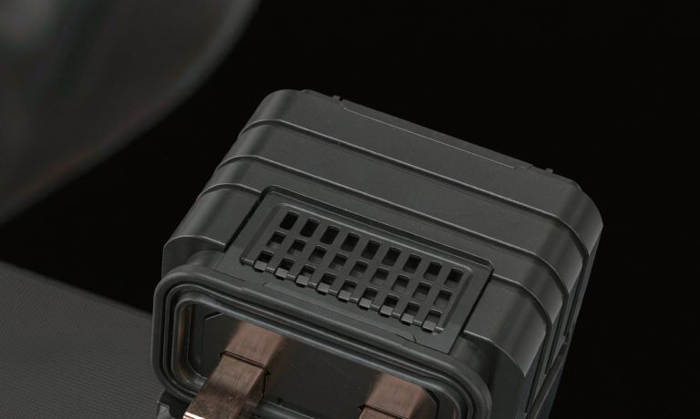
- Contact resistance under 5 mΩ per blade terminal, verified after the full insertion-cycle test, typically 5,000–10,000 cycles. Rising contact resistance shows up to the user as lost power and to the pack as a hot spot.
- Plating chosen for the environment. Tin is economical, gold-flashed contacts hold resistance better in humid and corrosive conditions. On outdoor tool platforms the upgrade usually pays for itself in returns avoided.
- IP54 as a floor, IP65 where specified, per IEC 60529, with gasket compression designed to a real tolerance stack rather than assumed.
- Respect the vent-versus-water tradeoff. Cells need a path for pressure relief, but that path must not become a water path. I use labyrinth channels and drainage geometry so that any water that enters leaves by gravity and never pools on the PCB.
Build the Certification Plan Into the Design, Not After It
Retrofitting compliance is the most expensive way to fail. My design reviews carry the test plan from day one:
- UN 38.3, tests T.1–T.8 — altitude, thermal cycling, vibration, shock, external short, impact/crush, overcharge and forced discharge. Non-negotiable for shipping any lithium ion battery product.
- IEC 62133-2 — safety requirements for portable sealed secondary lithium cells and batteries.
- IEC 62841 — the electrical safety family for hand-held motor-operated power tools, which governs the tool-plus-pack system.
- UL 2054 and UL 1642 — household and commercial battery and lithium cell standards for North American market access.
- IEC 60068-2-6 and 60068-2-27 — sinusoidal vibration and mechanical shock, which are where marginal welds and unretained wiring reveal themselves.
Beyond the certificates, I run design verification cycle-life testing at the customer’s real duty profile, not a lab-friendly 1C, holding the design to 80% capacity retention at 500 cycles minimum. A pack that certifies but fades to 70% in 300 jobsite cycles is still a failed design.
Design for Manufacturing, or the Design Does Not Exist
A pack that only a senior technician can build is not a product. When we move from prototype to production as a lithium battery manufacturer, the design has to become jig-friendly and mistake-proof.
- Poka-yoke the assembly. Cell holders keyed so reversed polarity is physically impossible. This one detail eliminates an entire class of catastrophic build error.
- Design the tolerance stack, do not discover it. Housing, holder, cell length variation and gasket compression accumulate; analyze the stack before the first tool is cut.
- Make test points accessible. End-of-line testing needs to read every cell group voltage, pack DCIR and NTC value without disassembly.
- Full traceability. Cell lot codes recorded against pack serial numbers. When a cell vendor has a bad lot, traceability is the difference between a targeted recall and a catastrophic one.
This is also where a custom battery solution outperforms an adapted stock pack. When cell choice, holder geometry, BMS thresholds and terminal design are all developed against one tool’s measured current profile, you gain runtime and thermal margin within the same envelope and weight, because nothing is oversized for a use case that does not apply.
Frequently Asked Questions
How many cells are in an 18V power tool lithium battery?
An 18 V nominal pack, often marketed as 20 V max, uses five cells in series. Compact packs are 5S1P with five cells; higher-capacity, higher-current packs are 5S2P with ten cells, or occasionally 5S3P with fifteen. A 36 V or 40 V max platform uses ten cells in series, and a 54 V or 60 V max platform uses fifteen.
What is the best cell for a power tool battery pack?
For nearly all tool applications, a high-drain 21700 with a DCIR in the 12–18 mΩ range and a 30 A or better continuous rating. Choose based on measured DCIR at the cold corner and rated continuous current, not on milliamp-hours. The extra capacity in a high-energy cell is not usable if the resulting voltage sag trips the tool’s undervoltage lockout.
Can I use high-capacity energy cells to get more runtime?
Only if the tool’s peak current is genuinely low, roughly under 20 A, as with lights, blowers or some drills. On impact tools and saws, the higher internal resistance produces excessive sag and heat, and the tool will cut out under load or overheat. This substitution requires full re-validation of the discharge envelope at low temperature and low state of charge before it can ship.
How hot is too hot for a tool battery pack?
Design for a cell surface ceiling of 60 C in worst-case normal use, with BMS shutdown at 70–75 C. Critically, measure the hottest cell in the middle of the array rather than a sensor on the circuit board, since the difference between those two locations can easily be 15–20 C.
Does a power tool battery need UN38.3 certification?
Yes. UN 38.3 testing is required to legally transport lithium batteries by air, sea or road, whether the pack ships alone, with a tool, or inside equipment. Plan for it early, because the T.1–T.8 sequence is destructive and needs dedicated sample allocation in the build schedule.
How long does a custom power tool pack design take?
For a new pack on an existing tool platform, expect roughly 8–14 weeks from measured current profile to production-ready design, with certification testing running four to eight weeks in parallel. A new voltage platform with novel tooling runs longer.
Closing Thought From the Bench
The best tool packs I have shipped were not the ones with exotic cells. They were the ones where we measured the tool first, chose cells on resistance rather than capacity, kept every cell immobile, put the sensor where the heat actually is, and wrote the test plan before the first prototype. Skip any of those and the field will find the gap, usually in the first cold snap.