
Drone Battery Integration for Mapping UAVs
Most teams treat a drone battery as a black box they bolt to the airframe and forget. After fifteen years building lithium packs for survey aircraft, I can tell you that is exactly where mapping programs lose data, time, and sometimes the whole aircraft. Drone battery integration for mapping UAVs is not the same problem as mechanical mounting — it is the discipline of making the pack a first-class member of the aircraft’s electrical and avionics system. When the battery, the harness, the flight controller, and the mapping payload all speak the same language, a survey flight is boring. When they do not, you find out at 120 meters over a wind farm.
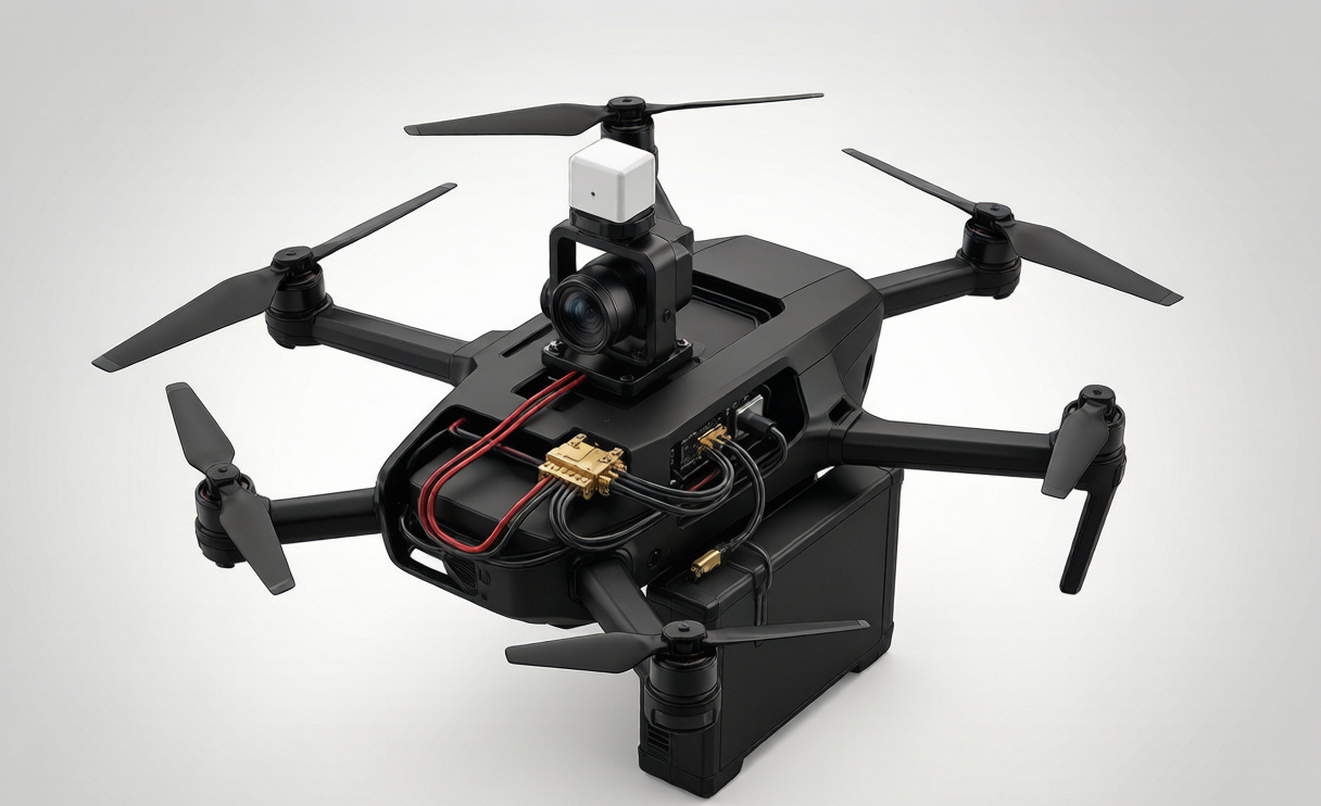
This article is the integration chapter of our mapping-UAV battery playbook. I am not going to re-litigate cell chemistry or cycle life — those are covered elsewhere. Here I will walk through the four things that actually break a mapping program at the system level: the harness, the data bus, the whole-aircraft power budget, and the bench test that proves the three are wired correctly before anyone arms the motors.
Integration Is Not Mechanical Design (Even Though It Touches It)
A common failure mode is to conflate integration with the bracket that holds the pack in. Mechanical integration — CG placement within 25–35% of mean aerodynamic chord, <60-second swap, conduction path to the airframe skin — matters, but it is settled engineering. System integration is the part people skip: how the pack electrically and digitally couples to everything else.
On a mapping UAV the payload is the customer. A gimbal, a multispectral camera, a LiDAR head, and an RTK receiver do not care how many watt-hours the drone lithium battery holds. They care whether the rail stays inside tolerance while the rotors spike at takeoff, whether they get clean, isolated 12 V / 24 V, and whether the flight controller knows the state of charge to the percent. Get those three wrong and your point cloud drifts, your images black out, and your pilot lands early. Integration is the work of guaranteeing all three.
The Harness: Connector, Pre-Charge, and Why Mating Counts
The single most abused part of any lithium battery installation is the connector. For a 6S–12S mapping pack the main power connector sees 100–160 A at takeoff and must survive the swap life of the program. We standardize on AS150 or XT150 shells with 8 AWG conductors and gold-over-nickel plating rated for 500–1,000 mate cycles. Contact resistance climbs from ~0.25 mΩ new to ~2.5 mΩ at end of life; that delta is the difference between 5 W and 25 W dissipated inside a 5 W-rated housing, so we retire a pack on the connector, not just on capacity.
Every mapping pack gets a pre-charge circuit before the main contact closes. On a >8S / >50 V pack the inrush into the flight-controller bulk capacitance can weld a contactor shut on the first plug-in. We size a pre-charge resistor plus a 400–2,000 µF reservoir through a 10–100 Ω path, hold for a few hundred milliseconds, then close the main contactor once the bus is within a few volts. The flight crew never sees it; the contactor does.
Pack DCIR stays below 10 mΩ at 1 kHz, with sag under 8% during a 3C / 10-second pulse, and interconnect resistance kept under 15% of total pack resistance — which is why we hold busbar interconnects to 1.5–1.8 mΩ. Those numbers are not trivia; they are what let the mapping rail hold voltage while all four rotors surge.
On the Bus: CAN / UAVCAN Telemetry Into the Flight Controller
A pack that only delivers volts is half a product. The other half is the data link. We put a BMS node on the aircraft’s CAN bus (UAVCAN / DroneCAN at 1 Mbps) that broadcasts pack voltage, per-cell minimum, current, temperature array, and state of charge at 1–10 Hz, with 100 Hz event logging on faults. The flight controller consumes that stream to drive the on-screen fuel gauge, to enforce the 25–30% reserve mandated by FAA Part 107 and EASA SORA for a mapping sortie, and to trigger a controlled return-to-launch before the pack becomes a liability.
The integration detail most vendors miss is galvanic and common-mode isolation between the high-voltage propulsion side and the telemetry side. We isolate the CAN transceiver and the sensor rail so a propulsion-side transient cannot inject noise into the RTK lock or the gimbal encoder. In our bench sweeps a clean isolated node keeps RTK float under a few centimeters; a non-isolated one loses lock on every rotor ramp. For a mapping deliverable measured in centimeters, that isolation is the difference between a usable survey and a reshoot.
Whole-Aircraft Power Budgeting for Mapping Payloads
Integration means budgeting the entire aircraft, not just the pack. A typical mapping payload draws: gimbal 20–80 W, thermal camera 20–45 W, LiDAR 15–40 W, companion computer 10–25 W, RTK 5–12 W, lighting 5–20 W, plus the propulsion baseload. A 12S 22 Ah NMC pack at 200–250 Wh/kg gives roughly 28 minutes of loiter with a 25–30% reserve — enough to clear a 250-hectare block at ~2.5 cm/px ground sample distance (GSD = pixel size × altitude / focal length) with 65–70% side and 70–80% forward overlap.
The integration trap is that the propulsion and payload budgets are coupled. A cold pack fades: usable capacity runs 100% at 25°C, 85% at 0°C, 70% at −10°C, 55–60% at −20°C. So a winter mapping mission needs either a 5–15 W pad heater held at 10–25°C (recovering roughly a third of the cold loss) or a derated flight plan. We fold that heater and its holdoff into the custom battery solution budget up front, because discovering it at the field edge is too late.
Chemistry choice is part of the same budget. NMC/NCA is the default for mapping (200–250 Wh/kg, 500–1,000 cycles). LFP (120–160 Wh/kg, 2,000–4,000 cycles) is the ground-cart and training-aircraft choice where mass matters less than cycle life. We do not pick chemistry in a vacuum; we pick it against the GSD, the altitude, and the season the customer actually flies.
Integration Verification: The Bench Harness Test Before First Flight
We never let a freshly integrated pack near an airframe until it passes a bench harness test. The procedure is deliberately boring: mate the connector to a load bank that replays the mission current profile (climb + cruise + payload spikes + RTL), watch sag stay under 8%, confirm the CAN node reports identical numbers to the local BMS, and verify the pre-charge sequence fires every time across 200 hot swaps. Only then does the pack earn an airframe integration slot.
Compliance is folded into the same gate. Every mapping pack ships qualified to UN38.3 T.1–T.8 and IEC 62133-2:2017, transported at ≤30% SoC per IATA PI 965/968, and labeled for the 100–160 Wh ceiling under FAA Part 107 / EASA SORA. Integration does not exempt a pack from transport and airworthiness rules — it makes them cheaper to prove, because the wiring is already documented and traceable by serial number.
Field Integration: Swap, Re-Zero, Re-Fly
The last integration step is the one the customer feels: turnaround. A mapping program lives or dies on sorties per day. We design the custom drone battery interface so a swap is a two-hand motion — one connector, one latch, one CAN auto-enumerate — with the flight controller re-zeroing SoC and re-establishing the telemetry link in under a second. No laptop, no recalibration, no ground crew. That is the payoff of treating integration as system engineering rather than a bracket.
Frequently Asked Questions
How do you size the pre-charge resistor for a mapping drone battery?
We target a pre-charge time of a few hundred milliseconds into the flight-controller bulk capacitance, using a 400–2,000 µF reservoir through a 10–100 Ω path on any pack above 8S or 50 V. The resistor wattage is sized for the inrush energy, not the steady state, and we verify the contactor closes with the bus within a few volts on every one of 200 hot-swap cycles during bench verification.
What CAN messages should a mapping drone battery broadcast?
At minimum: pack voltage, lowest cell voltage, pack current, temperature array, and state of charge at 1–10 Hz, with 100 Hz fault event logging. On UAVCAN / DroneCAN at 1 Mbps the flight controller uses that stream for the fuel gauge, the 25–30% reserve enforcement, and controlled return-to-launch. Isolation between the propulsion and telemetry sides is mandatory to protect RTK lock.
Can the same pack integrate both a LiDAR and an RGB mapping payload?
Yes, if the power budget accounts for both. LiDAR draws 15–40 W and RGB/gimbal 20–80 W; the pack must hold rail voltage through their combined spikes while the isolated sensor rail keeps each device clean. We budget the whole aircraft — payload, propulsion, and heater — and pick chemistry (usually NMC/NCA at 200–250 Wh/kg) against the GSD and altitude before committing the design.
How do you verify battery integration without a full airframe?
With a bench harness test: a load bank replays the mission current profile while we confirm sag stays under 8%, the CAN node reports match the local BMS, and the pre-charge sequence is reliable across 200 hot swaps. Only after that gate does the pack move to airframe integration, alongside UN38.3 T.1–T.8 and IEC 62133-2:2017 qualification.





