Drone Battery Design for Inspection UAVs: Power Quality, DC
After eleven years of designing lithium battery packs for industrial UAVs, the most frequently misdiagnosed problem I get called in to fix is not a pack that dies early. It is an inspection aircraft whose thermal camera shows faint horizontal banding, whose LiDAR returns drift by a few centimetres over a long loiter, or whose partial-discharge receiver picks up a phantom signal that turns out to be the pack’s own cell balancer. The customer opens a ticket about the payload. The root cause is sitting in the battery bay.
This article covers a side of drone battery design for inspection UAVs that rarely makes it into a datasheet: treating the pack as a power-quality component rather than an energy container. I will walk through the four levers my team actually adjusts — source impedance, ripple and transient budgeting, BMS and balancer emissions, and enclosure shielding — and the bench-plus-flight validation sequence we use to prove that a drone lithium battery will not corrupt the data the aircraft was bought to collect.
Why an Inspection Payload Turns the Pack Into an Electrical-Noise Problem
Inspection payloads have front ends that operate in the microvolt range. An uncooled LWIR bolometer resolves scene differences of 30–50 mK, a LiDAR avalanche-photodiode receiver integrates single-photon-scale returns, a corona camera counts UV photons against solar background, and a partial-discharge receiver deliberately listens in the 10 kHz–30 MHz window. Every one of those sensors shares a DC bus with four to eight motors that draw pulsed currents of 20–120 A through electronic speed controllers switching at 8–24 kHz.
That is a fundamentally different design problem from a racing or delivery platform. On a racing quad I optimise for burst power and thermal survival; on a delivery drone I optimise for cost per mission. On an inspection aircraft the sensor output is the product. A 2% capacity fade is commercially invisible. Forty millivolts of ripple sitting in the wrong frequency band can invalidate an entire transmission-line survey and force a re-flight, which in remote work costs more than the battery.
So we write electrical-noise requirements into every inspection-grade drone battery specification alongside the energy numbers. On our current 6S 21700 inspection platform — 25.2 V nominal, 355 Wh — the spec reads: broadband ripple at the payload input below 30 mV peak-to-peak during steady hover, transient bus excursion below 150 mV during a gimbal slew or datalink burst, and conducted emissions at least 6 dB below the CISPR 25 class 4 envelope from 150 kHz to 30 MHz. Those three lines drive most of the decisions that follow.
Source Impedance: How Pack DCIR and Internal Layout Set the Sag Envelope
A drone lithium battery is a voltage source with a non-trivial and frequency-dependent impedance, not an ideal rail. The total source impedance the payload sees is the cell contribution plus every interconnect in the path. Measured on our bench at 25 °C: a good high-drain 21700 cell sits near 18 mΩ DC internal resistance, so a 6S3P arrangement contributes 6 × 18 / 3 = 36 mΩ. Nickel-strip welds and the busbar add 4–6 mΩ. A 10 AWG 300 mm output pair adds roughly 2 mΩ. An AS150 or XT90 contact pair starts at 0.25–0.6 mΩ but can double after a few hundred mating cycles. Realistically the pack presents about 45 mΩ.
Run the arithmetic that matters to the payload. A 40 A motor transient across 45 mΩ is a 1.8 V step on the bus. Most payload DC-DC converters regulate that away, but line-transient rejection in the final low-dropout stage feeding an analog sensor is typically only 40–60 dB at 10 kHz, so a few hundred microvolts still reach the front end. Worse, cell impedance is not flat: double-layer capacitance shunts the charge-transfer resistance above roughly 1 kHz while the diffusion term dominates below 10 Hz, which leaves the pack a mediocre decoupler in the 1–20 kHz band — exactly where the ESC switching harmonics live.
The design responses are ordered by cost. Going from 3P to 4P drops the cell contribution to 27 mΩ but adds mass and pushes the airframe’s energy budget. A laser-welded nickel-copper sandwich busbar cut our interconnect term from 5.5 to 2.1 mΩ for a 4% cost adder. The cheapest fix is topology: give the payload a dedicated tap at the pack terminals in a star arrangement instead of daisy-chaining it off the ESC distribution board. On a utility-inspection platform last year that single change reduced ripple measured at the sensor input from 62 to 24 mV peak-to-peak with no change to cells, mass, or price.
Ripple and Transient Budgeting: Where the Decoupling Actually Belongs
When I scope a custom battery solution for an inspection airframe, I allocate the noise ceiling like a mechanical tolerance stack. If the payload can accept 30 mV, I give the pack and harness 40% of it, the ESC bus and distribution 40%, and the payload’s own internal filtering the remaining 20%. That means the pack itself must not contribute more than about 12 mV. Writing the budget down early prevents the usual outcome, where three subsystem teams each assume someone else owns the filtering and nobody does.
Inside the pack we place two 470 µF 35 V polymer capacitors (18 mΩ ESR each) plus four 10 µF ceramics directly across the output busbar, with a small common-mode choke on the dedicated payload tap. The trade-off is inrush: roughly 950 µF connecting to a live 25.2 V bus will draw a several-hundred-amp spike that erodes contacts and can nuisance-trip the BMS. We gate it with a MOSFET pre-charge path — 100 Ω for 50 ms before the main FET closes — which holds inrush under 8 A, and we specify anti-spark connectors so field crews are not relying on technique.
Harness discipline delivers more improvement per gram than any component. Reducing the separation of the 300 mm output pair from 40 mm to 6 mm shrinks the current loop area and dropped our measured radiated field by about 11 dB at 20 MHz. We route the payload feed at least 50 mm from motor phase leads, or crossing them at 90 degrees where clearance is impossible. And we insist on a single-point ground reference at pack negative, because a ground loop that puts even a few millivolts of motor return current into the sensor’s analog reference will produce artifacts that look exactly like a failing sensor.
EMC Co-Design: Conducted and Radiated Emissions From the BMS
The battery management system inside a drone battery is itself an aggressor, and this is the part most pack suppliers never characterise. Switched-capacitor or resistive balancers chop cell currents, the coulomb-counting fuel gauge runs a modulator, and the housekeeping DC-DC that powers the MCU switches continuously. An earlier BMS generation of ours used a 300 kHz buck with no spread-spectrum modulation, and its harmonics landed squarely inside the window used by a customer’s partial-discharge payload. We fixed it three ways: moved to a 2.2 MHz converter with spread spectrum, added a pi filter on its input (1 µH with 4.7 µF either side), and inhibited cell balancing in flight unless imbalance exceeds 30 mV, deferring it to charge and storage. The firmware change alone removed a 27 dBµV peak and cost nothing.
Pre-screen against a real limit line rather than eyeballing scope traces. We measure conducted emissions with a LISN on the payload feed against CISPR 25 class 4, run a radiated scan at 1 m in the style of MIL-STD-461G RE102, and use IEC 61000-4-4 and 61000-4-6 injection for repeatable susceptibility checks. For operators working near crewed aviation infrastructure, RTCA DO-160G Section 21 categories M and H are the recognised airworthiness references and worth designing toward even when not formally required. Our current pack platform measures 8–12 dB below the class 4 envelope across 150 kHz–30 MHz.
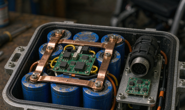
Shielding is the last lever, and carbon-fibre airframes are not the answer — they are conductive but lossy and inconsistent. We treat the battery case as a controlled aperture instead: an aluminium foil-laminate liner inside the polycarbonate shell, bonded to pack negative at exactly one point, a conductive gasket under the lid, and no unfiltered conductor leaving the shield boundary. There is a thermal cost, since a foil liner slightly reduces radiative cooling, so every shielded build is re-validated against our 45 °C warn and 60 °C de-rate thresholds during a full-duration loiter.
The Validation Sequence That Proves Payload Compatibility
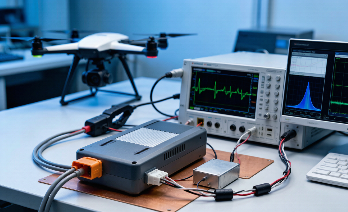
Bench validation runs in five steps. First, static ripple capture at 0, 25, 50 and 100% load with an electronic load pulsing at 1, 5 and 20 kHz. Second, a source-impedance sweep from 10 Hz to 100 kHz using four-wire AC injection, which produces the |Z| plot that tells you where the pack stops decoupling. Third, inrush capture on connection. Fourth, conducted emissions with the LISN. Fifth, and most valuable, payload-in-the-loop: the customer’s actual sensor recording live while the electronic load replays a real flight current profile pulled from telemetry.
Flight validation is a minimum of three sorties. A clean hover with the sensor recording establishes the in-air noise floor. A representative inspection profile with the gimbal slewing and the datalink transmitting at full power exercises the worst coupling case. A cold start between −5 and +5 °C is mandatory because DCIR rises to 1.8–2.2× its 25 °C value, which widens the sag envelope by the same factor. Acceptance criteria: sensor SNR degradation under 1 dB against a ground-truth reference, no artifacts identified in a blind review of 30 frames, and bus excursion inside 150 mV.
None of this displaces the normal safety and transport envelope. Every pack still qualifies to UN 38.3 tests T.1 through T.8, certifies to IEC 62133-2 (with IEC 62619 for the larger industrial units), ships as UN 3480 or UN 3481 Class 9 at 30% state of charge or below, and is sized deliberately around the 100 Wh and 160 Wh thresholds that FAA and EASA rules apply to carried spares, with IATA Section II packing for the sub-100 Wh units. Once a build passes, we freeze the configuration: cell source, busbar geometry, BMS firmware revision, filter bill of materials, and harness dressing. Changing any of those is a re-test, not a paperwork revision. That frozen, measured baseline is what turns a generic pack into a defensible custom battery solution for a specific inspection aircraft.
Frequently Asked Questions
How much ripple can an inspection payload actually tolerate?
Ask the payload vendor for a number and, if they cannot give one, measure it. In our experience most gimbal-mounted thermal and visual sensors are comfortable below 50 mV peak-to-peak, LiDAR units want under 30 mV, and partial-discharge or corona receivers can need under 10 mV in their listening band. The band matters as much as the amplitude: 100 mV at 2 MHz is often harmless while 20 mV at 15 kHz is not.
Does a bigger battery fix noise problems?
Partly, and for the wrong reason. Adding parallel cells lowers DC internal resistance, which reduces sag, but it does little above a few kilohertz where the capacitive shunt already dominates. You pay the mass penalty and keep the artifact. Fix the loop area, the tap topology and the BMS switching frequency first — those are usually free or nearly free — then size the lithium battery for the endurance the mission actually needs.
Should the payload run off the pack directly or off the ESC bus?
Directly off a dedicated pack tap, in a star topology, wherever the airframe allows it. Sharing the ESC distribution bus puts the sensor’s supply at the electrical node with the highest switching activity on the aircraft. A separate tap with its own common-mode choke is the single highest-value change I make on retrofit projects.
Do I need formal EMC testing for a commercial inspection drone?
Full qualification is usually not mandated for the battery alone, but pre-compliance measurement is still the cheapest insurance you will buy. A LISN scan against CISPR 25 class 4 takes an afternoon and catches the BMS converter harmonics that otherwise surface as unexplained payload artifacts three months into a contract. If you operate near airports or crewed aviation systems, design toward DO-160G Section 21 from the start.
Does cell balancing during flight matter?
It can matter a great deal. Resistive and switched-capacitor balancers create chopped currents inside the pack, and on sensitive receivers we have traced discrete emission peaks directly to balancing activity. Our firmware now inhibits balancing in flight unless imbalance exceeds 30 mV and performs the work during charge and storage instead. Pack health is unaffected and the noise disappears.
If you are specifying a drone battery for an inspection platform, put the noise requirements in the purchase specification next to the capacity and C-rate figures, and ask your supplier for a source-impedance plot and a conducted-emissions scan. A supplier who can produce both has actually characterised the pack. One who cannot is selling you cells in a box and leaving the power-quality engineering to your payload team.