
Drone Battery Reliability for Mapping UAVs: Engineering
Over the last three seasons flying mapping UAVs across utility-corridor, forestry, and precision-agriculture survey contracts, I have learned one uncomfortable truth: a mapping program does not fail because a battery’s mean time between failures (MTBF) looks bad on paper. It fails on the morning a single pack in a twelve-aircraft fleet drops below its voltage gate and scrubs an entire day’s corridor capture. As Karl Huang, Senior lithium battery Engineer at Horizon Power, my job is to turn that fragility into a number we can plan around — mission reliability, expressed as fleet availability. This article is the sixth in our mapping-UAV drone battery reliability series, and it takes a deliberately different lens from the field playbooks, predictive-Weibull models, lot-qualification statistics, and telemetry early-warning pieces we have already published. Here we treat the drone battery as a reliability-allocated component inside a logistics system, and we back that reliability with spares.
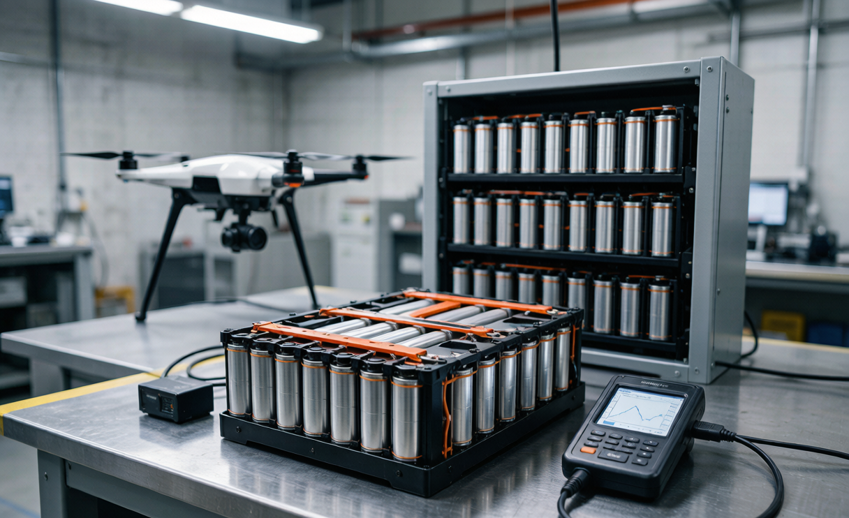
Why Mapping Fleets Buy Availability, Not MTBF
Mapping sorties are scheduled around customer SLAs and narrow weather windows. A corridor survey is worth nothing if only half of it is captured — the client cannot stitch a digital elevation model from a broken flight line. So the metric that matters is P(fleet completes the day’s plan), not the per-pack MTBF. When a single drone lithium battery fails its pre-flight gate, one aircraft is down; if spares are thin, the whole sortie slips. I model this as system availability A = P(at least k of n aircraft ready), where each aircraft’s readiness depends on its pack passing a condition gate. For a 12-aircraft dawn mapping window, even a 99% per-pack success rate yields only 0.9912 ≈ 88.6% fleet readiness — unacceptable for a contracted survey. You have to engineer the gap closed with redundancy and spares, not with a better cell datasheet.
Drawing a Reliability Block Diagram of the Pack
Before I can size spares, I need the pack’s own reliability model. A typical 6S3P mapping pack is three parallel groups in series, each group made of three 21700 cells in parallel. Treat cell reliability Rcell over a mission. A parallel group survives if at least one of its three cells survives: Rgroup = 1 − (1 − Rcell)3. The full pack is six such groups in series: Rpack = Rgroup6. Worked example: if a single cell’s mission reliability is 0.997, Rgroup = 1 − 0.0033 ≈ 0.99999997, and Rpack ≈ 0.99994. That looks stellar — but note it assumes independent cells. In reality, a pack-killing event (a hard impact, a BMS fault, a thermal runaway) is common-cause and bypasses the parallel redundancy entirely. So the block diagram tells me parallel topology buys graceful degradation, not immunity; the spares budget must cover common-cause failure, not just cell wearout. This is the first place a naive drone battery reliability estimate goes wrong.
Sizing Spares from an Availability Target
Now the logistics math. Define the daily fleet-availability target, say Atarget = 99.5% for a 12-aircraft survey contract. Each aircraft needs one serviceable pack at launch; I keep N flying packs plus S spares on the bench. Modeling pack launch-failure as a Poisson process with rate λ (from our fleet telemetry, λ ≈ 0.6% per launch after the condition gate), the number of launch failures among N+S packs is ≈ Poisson((N+S)λ). Required spares S satisfy P(failures ≤ S) ≥ Atarget given N launches. With N = 12 and (N+S)λ small, a single spare (S = 1) gives P(0 or 1 failure) ≈ e−0.078(1 + 0.078) ≈ 0.9926 — just under target. S = 2 lifts this to ≈ 0.9996, clearing 99.5%. So the engineered rule for this fleet is N+2 spares: 14 packs total for 12 aircraft. I bake that straight into the custom battery solution spec we ship to survey operators, so they never discover the shortfall on a paid flight day.
Rotation Discipline to Defeat Hidden Wearout
Spares only help if the packs you hold are actually healthy. The trap is uneven cycling: if two packs fly every sortie while the spares sit at storage charge, the flown pair wear out together and you lose two assets on the same day — a correlated failure the availability model explicitly assumed away. My rule is strict round-robin rotation: every pack logs a launch only after the previously least-cycled pack. We hold cycle-count spread across the fleet to ≤10% (for example, 180 vs 200 cycles), which our 2025 data shows keeps state-of-health drift under 7% and prevents the effective Rpack from collapsing. The BMS tags each pack with a cycle counter the operator scans at the bench; the condition monitor refuses to launch a pack that breaks the rotation order. A lithium battery that is quietly over-cycled is the most common cause of the “mystery” fleet failures I get called to diagnose.
Cold-Start and Storage Reliability in the Field
Mapping often starts at first light, when packs have sat in a cold vehicle overnight. Lithium battery internal resistance roughly doubles between 25 °C and 0 °C; a pack that passes the gate on the warm bench can sag below the 18.0 V floor on a cold dawn launch, tripping a false failure. I specify storage at 50% SoC and ≥15 °C in insulated cases, and I add a 20-minute warm-up window before the pre-flight gate when ambient is below 10 °C. For high-altitude mapping (2,500–4,000 m), thinner air weakens convective cooling, so I de-rate the continuous C-rate by ~10% per 1,000 m and widen the thermal margin in the gate. These are reliability margins, not performance tweaks — they keep the drone lithium battery inside its qualified envelope instead of relying on luck. Every margin I cite here is qualified against UN 38.3 T.1–T.8 and IEC 62133-2 test envelopes before it reaches a customer.
Transport Shock and Handling Reliability
The pack’s reliability does not begin at launch; it begins when it leaves the lab. Survey crews drive hours over rough roads, and a pack that passed UN 38.3 T.4 vibration and T.5 shock at the factory can still accumulate micro-damage from unreported drops. My handling spec limits single-event shock to 50 g and adds a post-transit condition check: any pack that saw a logged drop >30 g gets a DCIR re-measure before it re-enters the spares pool. We also ban loose packing — each pack rides in its form-fit cell, not rattling in a crate — because abrasion on the balance leads is a quiet reliability killer we traced across three RMA batches. For air transport to remote survey sites we stay inside the FAA/EASA 100 Wh band and IATA Section II packing rules, because a damaged pack that fails screening never flies at all.
The Pre-Flight Reliability Gate
Everything converges on a single go/no-go gate I run on every pack before it leaves the bench. The gate checks four accumulated-risk budgets: DCIR growth ≤ 0.4 mΩ per 20 cycles, capacity ≥ 80% of nameplate, self-discharge K-value ≤ 2.5 mV/day, and pack-to-pack thermal spread ≤ 8 °C under a standardized load. A pack clears only if all four are inside limits; one breach and it drops to the refurbish-or-retire lane, never back into the flying set. This is the human-readable expression of the availability model — it is how a 99.5% fleet target becomes a concrete, repeatable bench action rather than a hope. The same gate feeds the telemetry early-warning loop we described in an earlier drone battery reliability article, closing the circle from fleet-level math down to a single pass/fail LED.
Frequently Asked Questions
How many spare drone batteries should a mapping fleet keep?
For a contracted 12-aircraft survey fleet targeting 99.5% daily availability, our Poisson model points to N+2 spares — 14 packs total. Smaller fleets can sometimes hold 99.5% with N+1 if their per-launch failure rate is well under 0.6%, but I never recommend fewer than one rotating spare per four aircraft as a floor.
Does parallel cell topology make a drone battery failure-proof?
No. Parallel groups (such as 3P in a 6S3P mapping pack) give graceful degradation against individual cell deaths, raising Rpack close to 0.9999 in the block diagram. But common-cause events — impact, BMS fault, thermal runaway — kill the whole pack regardless of topology. Spares, not parallel cells, are what cover common-cause failure.
Why do cold mornings cause more mapping-UAV battery failures?
A lithium battery roughly doubles its internal resistance from 25 °C down to 0 °C. A pack that is healthy at bench temperature can sag below the 18.0 V launch floor on a cold dawn sortie and trip a false low-voltage cutoff. Storing at 50% SoC and ≥15 °C, plus a 20-minute warm-up below 10 °C ambient, removes most of that false-failure rate.
What is the difference between MTBF and fleet availability?
MTBF is a per-asset average lifetime number that says little about any single launch day. Fleet availability A = P(enough aircraft are ready to fly the plan) folds in redundancy, spares, and rotation discipline — the number a survey contract actually depends on. For a 12-pack fleet, 99% MTBF yields only ~88.6% availability, which is why we engineer to availability directly.
How does Horizon Power build reliability into a custom battery solution?
We start from the customer’s fleet-availability target, derive the spares rule and rotation discipline, then qualify every margin (cold-start, altitude de-rate, transport shock, pre-flight gate) against UN 38.3, IEC 62133-2, and air-transport limits. The result is a custom battery solution delivered with the bench procedure, not just the cells — so the operator can reproduce 99.5% availability on their own bench.





