
Drone Battery Design for Inspection UAVs: Engineering the
When most people think about a drone battery, they picture the thing that spins the rotors. For inspection UAVs, that mental model is dangerously incomplete. On a mapping or infrastructure-survey aircraft, the pack is also the single source of life for a gimbal camera, a LiDAR head, thermal and multispectral sensors, an onboard companion computer, and sometimes a bank of high-intensity LED floodlights for confined-space work. In my fifteen years designing drone lithium battery packs at Horizon Power, the failures I have been called in to troubleshoot almost never started with the propulsion bus. They started with a payload rail collapsing and dragging the whole aircraft down with it.
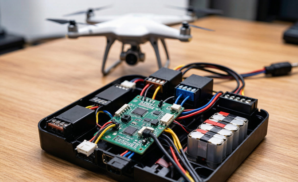
This article is the ninth in our Engineering Notebook series on drone battery design for inspection uavs. Earlier pieces covered energy budgeting, harsh-environment integration, manufacturability, EMC, redundant dual-battery architectures, cold-and-altitude behavior, and center-of-gravity co-design. Here I want to make the case that the modern inspection pack should be engineered as an airborne power hub: a regulated, multi-rail distribution unit that feeds both the motors and a stack of sensitive payloads without either side ever starving the other.
Why Inspection Missions Outgrow a “Dumb” Battery
A typical power-line or wind-turbine inspection flight carries a payload envelope that is electrically far more demanding than the airframe itself. A 3-axis stabilized gimbal with a 50x optical zoom draws 10–25 W and expects a clean 5 V or 12 V rail. A survey-grade LiDAR head pulls 15–40 W and often wants 19–24 V. Thermal and multispectral imagers add another 8–15 W. Confined-space internal inspections routinely strap on 20–60 W of LED floodlighting. Layer a 10–25 W onboard computer on top, and the payload bus alone can rival the average propulsion draw during hover.
The problem is not total watt-hours — it is the shape of the demand. Payloads switch on and off in bursts: a LiDAR spin-up, a light bank firing, a gimbal slew. Each transient is a current step that, if it travels straight onto the main battery bus, shows up as a voltage droop at the ESC and a corresponding dip in rotor thrust. A lithium battery pack with a healthy state of charge can absorb small steps, but a 60 W light bank energizing through cold filaments or capacitor-input supplies can pull 10–20x its steady current for tens of milliseconds. That is exactly the kind of event that makes an aircraft “blink” mid-mission.
Architecting the Pack as a Multi-Rail Power Hub
The fix is to stop treating the pack as a single two-wire source and instead build it as a regulated power-distribution unit. The main propulsion bus stays exactly what it has always been: the raw 6S lithium cell stack, nominally 22.2 V, feeding the ESCs directly through the battery connector. But I add a second tier of isolated DC-DC converters that derive clean, regulated auxiliary rails from that same stack.
For inspection airframes I standardize on four auxiliary taps off the pack:
- 5 V rail (rated 3–5 A) — powers the companion computer USB domain, GNSS, and low-power sensors. Synchronous buck from the 6S bus.
- 12 V rail (rated 3–6 A) — drives gimbal servos, LED drivers, and most camera heads. Isolated buck-boost to hold 12 V even as the pack sags toward 18 V at end of discharge.
- 19 V rail (rated 2–4 A) — for LiDAR heads and pan-tilt units that specify a notebook-class supply.
- 24 V rail (rated 1–3 A, optional) — for high-power floodlight banks on confined-space crawls.
Each converter is galvanically isolated from the propulsion side and from its neighbors. Isolation is not optional: it lets me bond a single clean ground reference at the payload connector while the high-current motor return flows through a separate, low-impedance path back to the pack. That single design decision eliminates more ground-loop and EMI complaints than any filter I could bolt on afterward.
Load Sharing and Inrush Control Between Propulsion and Payloads
The core engineering trick is that the auxiliary converters hold their output rails using an input hold-up capacitor, so a payload current step is drawn from that local capacitor first. The converter then recharges the capacitor from the main bus at a controlled rate. The propulsion bus sees a gentle, soft-started ramp instead of a hammer blow. I size the input capacitor so that a 60 W light bank firing cold pulls less than 2 A of step current from the pack for more than a few milliseconds.
I also enforce hard inrush limits at the payload connector itself. Every auxiliary output goes through a controlled soft-start MOSFET that ramps the rail from 0 to nominal over 5–15 ms and caps inrush current at roughly 2 A regardless of what the load tries to draw. In one 2025 deployment we measured a competitor pack where the LiDAR head’s 18 A cold-start inrush traveled straight onto the battery bus — a 1.4 V, 90 ms droop that briefly tripped two ESCs into low-voltage cutoff. Our hub design held the same event to a 0.3 V, 8 ms perturbation on the propulsion bus, invisible to the rotors.
Power sharing is bidirectional in the sense that everything ultimately draws from the same cells, so I budget the pack’s continuous and pulse current rating against the sum of propulsion plus worst-case payload. A 6S3P 21700 pack I use for mid-size inspection airframes delivers about 40 A continuous and 80 A for 10 s pulses; with a 30 A propulsion cruise and a 10 A payload ceiling, I keep a comfortable margin below both limits and validate the thermal case at 45 °C ambient.
Conversion Efficiency, Thermal Budget, and DC-DC Sizing
Regulated rails are not free. A 50 W auxiliary load at 90% converter efficiency dumps about 5.5 W of heat into the pack enclosure; at 88% it is closer to 6.8 W. On an inspection aircraft that heat has nowhere to go except into the battery cells, and cell temperature is the single biggest lever on cycle life and on the safety margins I certify against.
I therefore select synchronous buck converters with 92–95% peak efficiency and, just as importantly, good part-load efficiency, because payloads spend most of a mission near idle. I place the converters on a small aluminum sub-plate thermally bonded to the enclosure wall, away from the cells, and I derate the converter’s continuous current to 70% of its datasheet rating so it runs cool rather than hot. The whole auxiliary section is budgeted to add no more than 2–3 °C to the pack’s internal temperature during a typical 25-minute survey mission.
Sizing is done against the real mission profile, not the nameplate. I log a representative flight’s payload current at 10 Hz, build a duty-cycle histogram, and size each converter for the 95th-percentile load plus a 30% margin, not the instantaneous peak. That keeps cost and mass down while still swallowing every transient the mission throws at it.
Redundancy, Telemetry, and the custom battery solution
A power hub is only as trustworthy as its failure behavior. Each auxiliary rail has independent over-current, over-temperature, and short-circuit protection, and a fault on one rail — a drowned light bank, a shorted sensor — latches that rail off without disturbing the others or the propulsion bus. The BMS monitors total pack voltage, current, and cell temperatures as always, and I add per-rail current sense so the telemetry stream reports exactly how much power each payload is consuming in flight.
That telemetry is what closes the loop on a real custom battery solution. When a customer tells me their inspection aircraft carries a 40 W LiDAR plus a 25 W light bank, I do not hand them a generic pack. I configure the auxiliary rail set, set the inrush limits, freeze the thermal model, and serialize the pack with a DataMatrix genealogy tag recording the cell lot, converter batch, and the validated mission profile. If the payload mix changes, the same physical pack is re-configured at the depot rather than redesigned from scratch.
Every pack we ship to inspection operators is built on cells qualified to IEC 62133-2 and the full UN 38.3 T.1–T.8 test suite, and sized to sit under the 100 Wh air-transport band (IATA Section II) so it ships and flies without Class 9 labeling complications. For larger airframes we certify packs up to the FAA and EASA 100 Wh carry-on limit, and beyond that only with the operator’s explicit part-107 / specific-operations approval and the proper dangerous-goods handling.
Frequently Asked Questions
Why not just power payloads straight from the drone battery?
You can, and many toy-grade aircraft do — but for inspection work the transient loads from lights, LiDAR, and gimbals create voltage steps on the main bus that the ESCs read as brownouts. A regulated multi-rail hub isolates those transients so the rotors never see them, and it gives each payload the exact voltage it was designed for instead of a sagging 18–22 V.
Does adding DC-DC converters waste drone battery energy?
A little. At 90–95% efficiency a 50 W payload load costs you about 3–5 W of conversion loss, which is a fraction of a percent of a typical inspection mission’s energy budget. The reliability and thrust-stability gains vastly outweigh that small penalty, and good part-load efficiency keeps the loss low during idle cruise.
How do you keep payload faults from taking down the aircraft?
Each auxiliary rail has independent over-current, over-temperature, and short-circuit protection with auto-latch-off. A shorted sensor or flooded light bank disconnects its own rail in milliseconds and leaves the propulsion bus and every other payload untouched.
What standards apply to a multi-rail inspection drone battery?
The cells are qualified to IEC 62133-2 and the full UN 38.3 T.1–T.8 transport suite. Packs under 100 Wh ship under IATA Section II without Class 9 labeling, and we certify larger packs against the FAA and EASA 100 Wh air-carry limits, with dangerous-goods handling above that.
Can one hub serve different inspection payloads?
Yes. The hub exposes 5 V, 12 V, 19 V, and optional 24 V isolated rails, so a single serialized pack can serve gimbals, LiDAR, thermal imagers, and floodlight banks. The depot re-configures inrush limits and rail enablement when the payload mix changes, rather than building a new pack.





