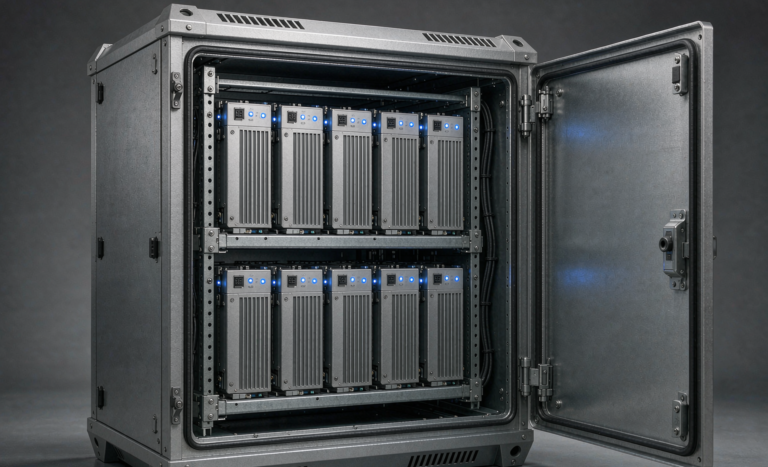
Lithium Battery Design for UPS Systems
When a data center, hospital, or factory loses grid power, the uninterruptible power supply (UPS) is the only thing standing between the load and a hard shutdown. For most of my career the backup layer inside those systems was sealed lead-acid (VRLA), but over the last six years I have redesigned dozens of UPS banks around a lithium battery core. The reason is simple: a well-engineered lithium battery design for UPS systems delivers three to five times the cycle life, roughly half the footprint, and a fraction of the maintenance overhead of the flooded or VRLA alternative. This article walks through how I actually specify and build those packs, from cell chemistry to cabinet cooling, based on field deployments I have commissioned myself.
Why UPS Systems Are Moving From VRLA to Lithium-Ion
The economic case for a lithium-ion battery in UPS duty is not the upfront price tag, it is the total cost across the service life. A typical VRLA string is rated for 300 to 500 cycles at 80% depth of discharge, and in a hot electrical room it often dies well before its nominal five-year calendar life. A properly balanced LiFePO4 (LFP) pack I design for the same application is rated for 3,000 to 6,000 cycles and a 10-year calendar life. When you amortize replacement labor, floor space, and the risk of a surprise failure during a utility sag, the lithium battery wins on every line item.
There is also a footprint argument. A 10 kWh LFP module I shipped for a regional hospital weighed 92 kg and occupied a 3U rack slot. The VRLA equivalent needed two 12U cabinets and weighed over 300 kg. In a congested switch room that space saving alone justified the conversion project.
From a maintenance standpoint the difference is even starker. VRLA demands quarterly impedance testing by a technician who travels to site, reads every jar, and logs trends by hand. A lithium-ion battery pack with a networked battery management system reports state-of-health automatically to the building management system, so the facilities team sees a drifting cell from their dashboard instead of discovering it during an annual outage drill. Over a 200-site estate that telemetry alone removed the bulk of my client’s unplanned backup failures.
Core Cell Selection and Pack Topology for UPS Duty
For stationary UPS backup, I standardize on LFP cells (LiFePO4) rather than NMC. The nominal 3.2 V plateau, flat discharge curve, and excellent thermal stability make them the safest fit for an unattended cabinet. I select cells with a continuous discharge rating at least 1.5x the UPS rated load, because inverter inrush and the step load at transfer time can briefly exceed steady-state draw.
The pack topology is almost always a 16S configuration (51.2 V nominal) for rack-mount UPS, or a 48V telecom-style string for smaller sites. I keep series groups in parallel (for example 16S4P) only when the runtime requirement pushes past 30 minutes at full load. Every parallel branch is fused individually so a single cell fault cannot cascade. As an engineer I treat each parallel path as an independent custom battery solution sub-module that must fail safely on its own.
- Cell grade: automotive or stationary-grade prismatic cells, ≥95% initial capacity matching within a group.
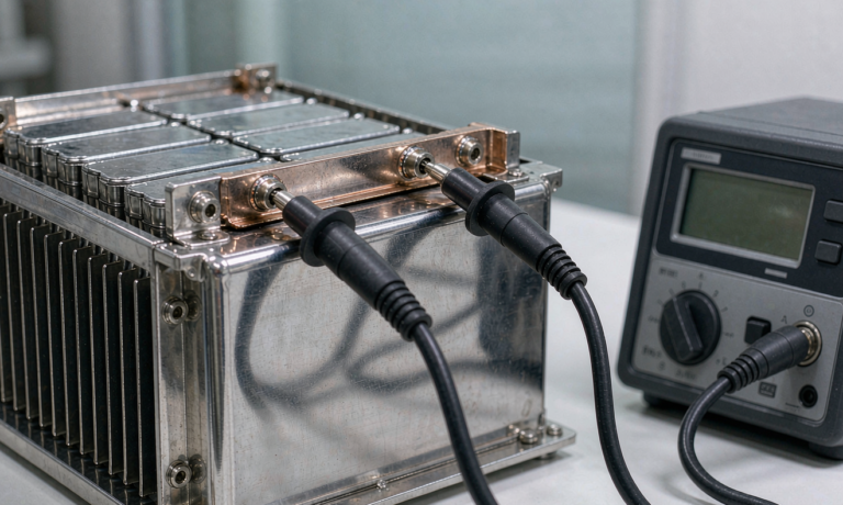
- Busbars: nickel-plated copper with torque-controlled joints, not soldered tabs, to survive the 5C transient peaks.
- Voltage window: 44.8 V cutoff (2.8 V/cell) to 58.4 V (3.65 V/cell) for LFP, with the BMS holding the upper bound.
Battery Management System Requirements for UPS Reliability
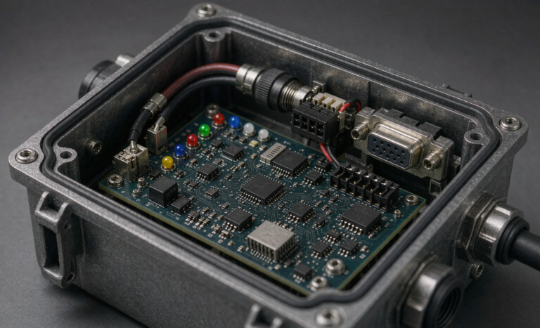
A UPS sits idle for 99% of its life and must be perfect on the one percent. That makes the battery management system (BMS) the most important component I specify. For UPS I require a BMS with:
- Per-cell voltage monitoring with <5 mV accuracy and active top balancing at >100 mA.
- Redundant current sensing on both charge and discharge paths.
- Contactor control with pre-charge to protect the UPS rectifier input.
- Isolation resistance monitoring against the cabinet chassis (IEC 62133 compliant).
- CAN bus or RS485 reporting so the UPS controller sees state-of-charge, temperature, and fault codes in real time.
In one deployment for a financial clearing house, the BMS caught a slowly drifting cell at 3.41 V versus 3.33 V on its neighbors and flagged it 11 weeks before it would have tripped the pack. That kind of early warning is exactly why I refuse to ship a UPS pack behind a passive protector board.
Thermal Management and Cabinet Design
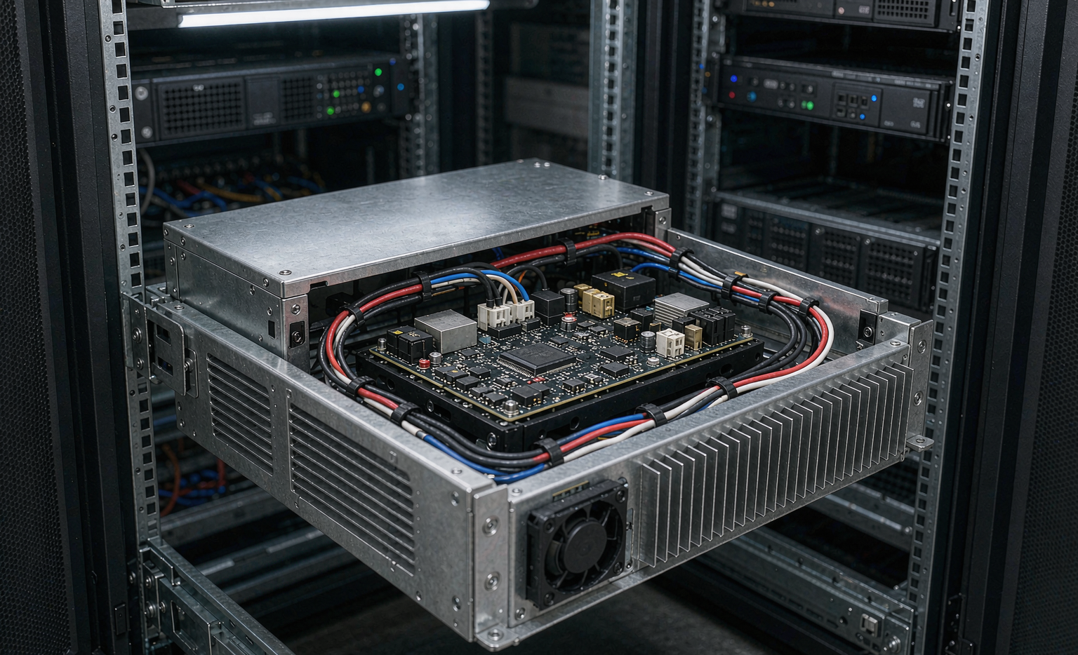
LFP is forgiving, but it is not immune to heat. I design the cabinet so that under a full 10-minute discharge the cell surface stays below 45°C even with the room at 35°C. That means aluminum cooling fins bonded to the cell faces, a minimum 10 mm air gap between modules, and either natural convection slots or a low-noise fan staged to kick in only above 35°C.
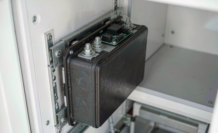
The enclosure itself meets IP20 for indoor rack use and IP54 for edge sites. I keep the lithium-ion battery modules away from the UPS inverter’s hot exhaust by orienting the rack so airflow pulls cool room air through the battery first. Cable management separates power bus from signal wiring to avoid the ground-loop noise that once corrupted a competitor’s BMS telemetry on a site I was called to fix.
Sizing, Runtime, and Parallel Redundancy
Sizing a backup pack starts from the load, not the battery. I take the UPS VA rating, convert to watts at the real power factor (often 0.8 to 0.9 for modern loads), then model the discharge at the actual C-rate. A 5 kW load on a 10 kWh pack is a 0.5C draw, which an LFP pack handles while holding voltage within 2% of nominal. That flat curve is why operators report steadier inverter behavior than they ever saw on VRLA.
For Tier-III style redundancy I parallel two independent lithium battery strings behind diode-isolated buses so either string can carry the full load. I never parallel packs through a single BMS, because a BMS fault would then take down the whole backup. Each string reports independently to the UPS, and the controller treats them as N+1.
Certification, Safety, and Commissioning
Every UPS pack I release is built to pass the certifications buyers now demand. The cells and pack carry UN38.3 for transport, and the design file documents IEC 62133 compliance for portable containment and IEC 62619 for stationary industrial use. For air-freightable spares I keep the energy density inside the ICAO/IATA 100 Wh and 300 Wh thresholds for the modules we ship. On the regulatory side, FAA and EASA guidance on lithium installations in critical facilities informs how I document venting and fire separation, even though a stationary cabinet is outside aviation scope, the discipline carries over.
Commissioning is where many projects fail. I run a 100% capacity verification at 0.2C before the pack goes live, a 24-hour float observation, and a single full transfer test with the actual load. Only after the UPS holds the load through a simulated outage do I sign the pack off. The custom battery solution is not done until it has proven itself under the real inverter, not just on a bench supply.
Return on Investment and When Lithium Does Not Pay
I am an engineer, not a salesperson, so I will be blunt about the boundary. A lithium battery design for UPS systems pays back fastest where cycles are frequent (poor grid, generator-dependent sites, or frequent mains switching) and where floor space is expensive. If a site experiences one clean utility event per decade and has a cavernous free plant room, VRLA may still be the cheaper capital choice. I model the crossover with the client before recommending chemistry, and I have walked away from lithium upgrades that failed the five-year TCO test. The honest answer protects the relationship and keeps the recommendations credible.
That said, the trend line is clear. Cell prices have fallen every year I have been specifying them, and the gap to VRLA on a lifetime basis has closed to the point that most new builds I touch now default to LFP unless a specific constraint blocks it. For any operator planning a 10-year horizon, designing the cabinet, busbars, and BMS around lithium from day one avoids a painful retrofit later.
FAQ
What is the typical lifespan of a lithium battery design for UPS systems?
A correctly specified LFP UPS pack delivers 3,000 to 6,000 cycles at 80% depth of discharge and a 10-year calendar life, compared with 300 to 500 cycles and roughly five years for VRLA. Real life depends on cabinet temperature and how often the site actually transfers to battery.
Can I replace VRLA with a lithium-ion battery without changing the UPS?
Often yes, but not blindly. The UPS rectifier must accept the LFP charge profile (constant-current then constant-voltage, with a 58.4 V ceiling), and the inverter must tolerate the lower internal resistance. I always verify the charge curve and add a pre-charge contactor so the rectifier inrush does not trip the BMS.
How do I size runtime for a lithium battery UPS?
Start from the true watts at the load power factor, then size the pack so the discharge C-rate stays at or below the cells’ continuous rating. A 0.5C draw on LFP holds voltage within about 2% of nominal, giving stable inverter behavior for 10 to 30 minutes of backup, which covers the genset start in nearly every facility I design for.
Is a lithium-ion battery safe in an unmanned electrical room?
Yes, with the right engineering. I use LFP chemistry, an IEC 62133-compliant BMS with isolation monitoring, individual branch fusing, and a cabinet kept below 45°C under discharge. The BMS provides early fault warning long before a cell becomes a hazard, which is why I never ship a UPS pack behind a passive board.