
Battery Solution Safety for Vehicles: An Engineer’s
Why Vehicle Battery Safety Is a System Property, Not a Cell Spec
When a fleet manager or an OEM asks me to design a battery solution for a vehicle, the first thing I tell them is that safety does not live inside the cell. A single pouch or prismatic cell that passes every datasheet test can still cause a pack-level fire if the surrounding architecture is wrong. In my fifteen years building packs for light EVs, AGVs, and even high-rate drone battery platforms, the failures I have investigated were almost never “bad chemistry” — they were bad balancing of mechanical, electrical, thermal, and firmware layers. This article is the field protocol I use to qualify a vehicle battery solution against real abuse, not a brochure specification.
Think of safety as a budget. You are allowed a certain probability of a single cell going into thermal runaway; your job is to make sure that event stays contained and never propagates. The cell sets the floor, but the pack design, the battery management system, and the certification program decide whether that floor holds on the road. Below I walk through the six layers I commission on every vehicle program.
Cell-Level Abuse Qualification: The UN38.3 and IEC 62133-2 Floor
Every cell I accept into a vehicle battery pack design must clear the UN38.3 transportation test suite (T.1 altitude, T.2 thermal, T.3 vibration, T.4 shock, T.5 external short circuit, T.6 impact, T.7 overcharge, T.8 forced discharge) before it ever reaches my bench. That is a transport floor, not a vehicle floor — but it is the first gate. On top of it I require IEC 62133-2 for the secondary lithium cells and IEC 62619 for the industrial module, because those standards add nail-penetration and thermal-abuse thresholds that UN38.3 alone does not.
Incoming cell grading is where most hidden safety margin is won or lost. I grade every lot on three numbers: capacity coefficient of variation below 6%, four-wire Kelvin DCIR (direct current internal resistance) coefficient of variation below 10%, and a self-discharge K-factor under 1.0 mV per day. A mismatched cell is a heater waiting to happen — under sustained cycling the weakest cell drifts to the voltage extremes first, and that is exactly where plating and thermal runaway begin. This is the same discipline I apply to high-C-rate lithium battery packs, where a 3 mΩ mismatch can collapse a 15C discharge.
Thermal Runaway Propagation Barriers (ECE R100 and GB 38031)
The defining safety question for any vehicle pack is simple: if one cell goes into thermal runaway, how long do you have before the next one does? ECE R100 — the UN regulation for electric power train safety — requires that propagation to other cells be delayed long enough that occupants can exit, with no fire or explosion outside the pack within a defined window. China’s GB 38031 sets a similar five-minute propagation-resistance target for passenger EV batteries. I design to those windows, not to the cell alone.
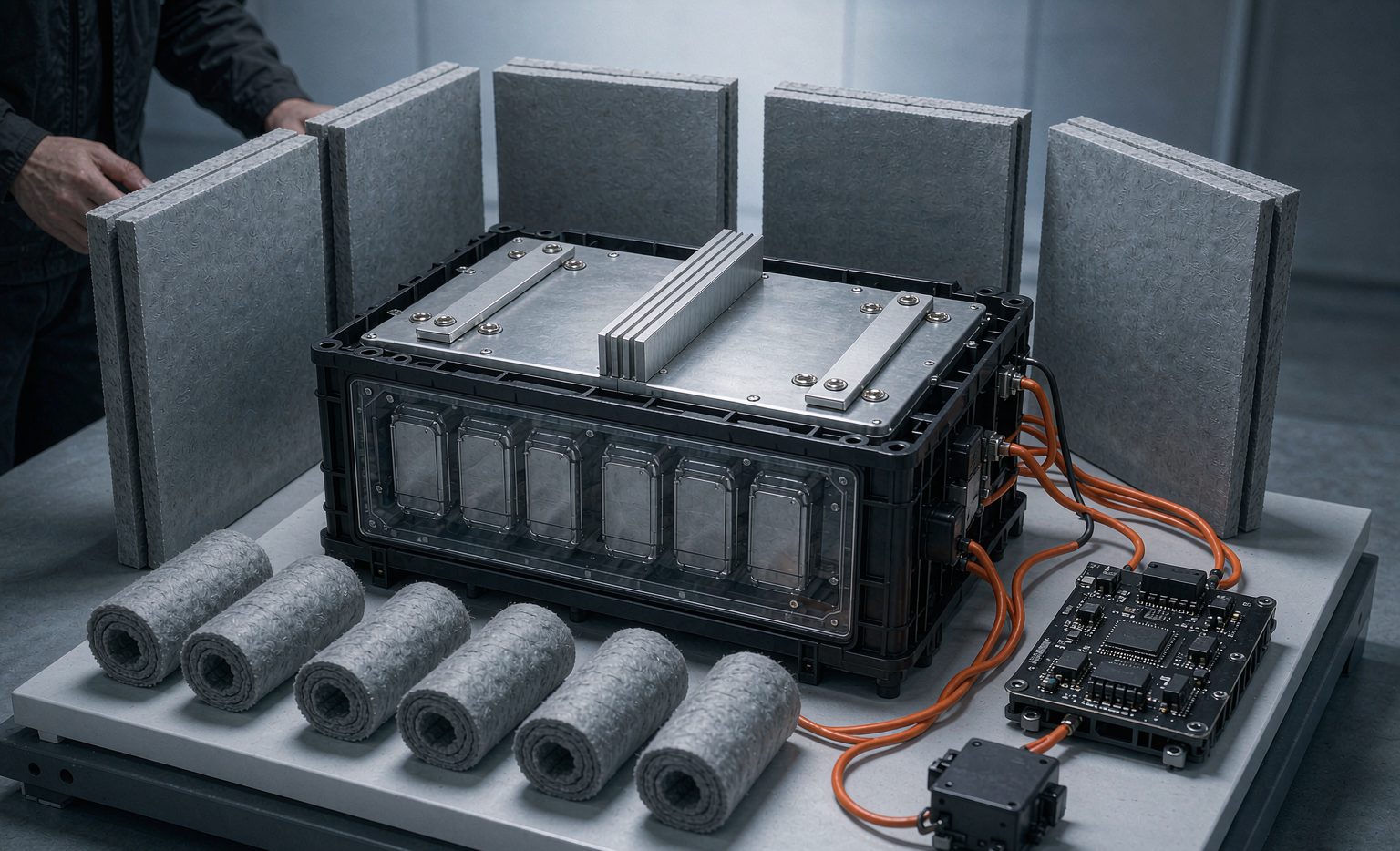
Chemistry choice buys you the first chunk of margin. A lithium iron phosphate (LFP) cell has a thermal runaway onset near 270 °C, roughly 60 °C higher than a nickel-manganese-cobalt (NMC) cell at about 210 °C. That 60 °C is the difference between a pack that survives a single-cell fault and one that does not. On top of chemistry I add physical barriers: aerogel blankets between modules, mica or ceramic-fiber end plates, and a vent path that routes off-gas away from adjacent cells. In a cell-to-pack architecture I shrink the cell gap deliberately and let the cooling plate act as a compression and heat-sinking member, holding 0.3–0.7 MPa preload so cells cannot bow under thermal expansion.
BMS Safety Architecture: Dual-Sense, Pyro-Fuse, and Isolation Monitoring
A custom battery solution is only as safe as the brain watching it. My vehicle BMS commissioning spec is non-negotiable. I require dual-sense voltage and temperature sampling so a single ADC fault cannot mask a hot cell. Overcurrent protection must act in under 200 ms, with a pre-charge stage that limits inrush on the contactor. For high-voltage packs I add a pyro-fuse — a pyrotechnic disconnect that severs the bus in milliseconds on a severe fault — and an isolation monitor that continuously checks resistance between the high-voltage rails and the chassis.
I also insist on a fault-tree that treats the contactor as a wear item. Weld-detect logic verifies the contactor actually opened; if it is stuck closed, the pack is flagged unsafe and locked out rather than silently continuing. Every fault is logged with a timestamp and a cell index, because the pattern of faults in the field is the single best predictor of the next failure. This is the same fail-safe philosophy I borrow from aerospace and drone battery programs, where a stuck contactor is not a nuisance — it is a loss of the aircraft.
Mechanical Isolation and Crash Intrusion (IP67, MIL-STD-810H)
Vehicles crash, vibrate, and drown — sometimes all on the same shift. I seal every vehicle pack to at least IP67 so a fording event or a pressure-washer does not push water into the high-voltage compartment. The enclosure is designed to absorb crash intrusion on the protected side while keeping the cell stack behind a crush zone. Vibration and shock are qualified against MIL-STD-810H method 514.8 (random vibration) and 516.8 (shock), because road spectra are brutally broad-band and a resonance in the busbar can fracture a laser weld over a million cycles.
That weld is the most under-rated safety component in the industry. I specify pure-nickel laser welds held under 0.15 mΩ with a pull strength above 25 N, validated to a process capability index (Cpk) of at least 1.67. A cold or porous weld is a local hot-spot generator. The same preload that controls thermal expansion also controls vibration fatigue, which is why I treat the mechanical stack and the electrical stack as one integrated design rather than two separate drawings.
Functional Safety and the Standards Stack (ISO 26262, IATF 16949, UL 2580)
For any production vehicle program the safety argument has to be documented, not just built. I work to ISO 26262 automotive functional safety, assigning an ASIL (Automotive Safety Integrity Level) to each safety-related function and tracing it from hazard analysis down to the line of firmware that implements it. The manufacturing quality system runs on IATF 16949 with APQP and PPAP gates, so the pack that ships is the pack that was validated. UL 2580 is the North American electrical safety standard for EV batteries and is part of the dossier I hand to a certification body alongside ECE R100 and GB 38031.
Transport of the finished pack is its own safety domain. I ship and handle under IATA Section II at 30% state of charge for air movement, and the same 30% SoC rule applies to FAA and EASA carriage of the smaller drone battery modules we build in the same facility — a consistent low-energy state removes the single biggest variable in a transport incident. None of this is optional paperwork; it is the proof that the system property called “safe” was designed on purpose.
My Commissioning Safety Checklist for Vehicle Battery Solutions
Before a vehicle battery solution leaves my lab I run a six-point commissioning safety pass, and I recommend every buyer demand the same evidence:
- Cell grading report — capacity CoV under 6%, four-wire Kelvin DCIR CoV under 10%, K-factor under 1.0 mV/day, with the lot genealogy in a DataMatrix code.
- Abuse qualification package — UN38.3 T.1–T.8, IEC 62133-2, IEC 62619, and the nail/overcharge thermal-abuse records, signed by the test lab.
- Propagation test — a single-cell thermal runaway with a verified no-propagation window meeting ECE R100 / GB 38031, documented with cell-by-cell temperature traces.
- BMS fault-tree validation — dual-sense check, under-200 ms OCP, pre-charge, pyro-fuse function, contactor weld-detect, and isolation-monitor resistance trend over 72 hours.
- Mechanical proof — IP67 ingress, MIL-STD-810H 514.8 / 516.8, weld Cpk ≥ 1.67, and a crush-intrusion simulation on the protected side.
- Functional-safety dossier — ISO 26262 ASIL mapping, IATF 16949 PPAP, UL 2580, and the IATA Section II 30% SoC transport declaration.
If a supplier cannot show you all six, you do not have a battery solution — you have a hope. The cost of closing these gaps after a field incident is always higher than the cost of designing them in.
Frequently Asked Questions
What is the single most important safety factor in a vehicle battery solution?
Thermal-runaway propagation resistance. A single cell failing is unavoidable over a pack’s life; what matters is that the event stays inside one cell and gives occupants time to exit. That comes from chemistry choice (LFP’s ~270 °C onset), physical barriers (aerogel, mica), and a vent path — not from the cell datasheet alone.
Is UN38.3 enough to certify a vehicle battery pack for safety?
No. UN38.3 is a transportation test that proves the cell or pack is safe to ship. For road use you also need IEC 62133-2 / IEC 62619 at the cell level and ECE R100, GB 38031, and UL 2580 at the pack level, plus ISO 26262 functional safety for production vehicles.
Why do you grade cells by internal resistance before building the pack?
DCIR mismatch is the leading silent cause of pack failure. A cell that is 10% higher in resistance heats faster under load, drifts to the voltage extremes, and becomes the initiation point for lithium plating and thermal runaway. Four-wire Kelvin grading below 10% CoV keeps the pack thermally balanced for its whole life.
How fast must the BMS disconnect a faulted pack?
For the protection functions I commission, overcurrent protection must act in under 200 ms, with a pre-charge stage limiting contactor inrush and a pyro-fuse available for severe faults that severs the high-voltage bus in milliseconds. Speed matters because the energy available in a vehicle pack is large enough to weld contacts or start a propagation event in well under a second.
Do you apply the same safety rules to drone batteries as to vehicle packs?
The principles are identical — cell grading, abuse qualification, fail-safe BMS, and isolation monitoring — but the packaging is tighter and the rate higher for a drone battery. I reuse the same UN38.3 / IEC 62133-2 / FAA-EASA framework and simply compress the footprint, which is why a custom battery solution built in our lab carries one consistent safety language across every platform.





