Home Energy Storage Integration for Cabins
I have commissioned home energy storage systems in cabins from the Adirondacks to the Carpathians, and I can tell you this: the battery is almost never the part that goes wrong. What goes wrong is the interface — the transfer switch that chatters, the generator that fights the inverter, the neutral bonded in two places at once, the DC cables that were sized by eye and run 30 °C hotter than anyone expected. A cabin is a uniquely unforgiving place to integrate a home energy storage system, because there is no utility to hide your mistakes and the nearest replacement part is a four-hour drive away.
This is the integration playbook I actually use. It is written for the moment you already know you want storage — the design and sizing decisions are behind you — and now you have to bolt that battery onto a building that was never designed for it, feed it from solar and a generator, and make it survive a winter with nobody on site. I will walk through topology, the inverter/charger interface, transfer switching and generators, grounding and surge, cold-climate behaviour, DC cable reality, and the commissioning sequence that catches the failures before they cost you a return trip.
Start the Integration With a Measured Load Audit, Not a Nameplate List
Every integration decision downstream — inverter continuous rating, surge rating, critical load panel layout, generator size — is only as good as the load data you feed it. Nameplate ratings are close to useless for this. A ½ hp submersible well pump might carry a nameplate of 750 W running and, for one to three seconds, demand 3–5× that on startup. A 4500 W resistance water heater is not a load you back up at all; it is a load you delete, because it alone would dictate a 6 kW inverter.
What I ask every customer to do before we talk about hardware is log the site for seven to fourteen days with a clamp meter or an inexpensive whole-home energy monitor. I want three numbers out of that log:
- Daily energy (kWh/day) — this sizes the battery and the array.
- Peak 15-minute average power (kW) — this sizes the inverter’s continuous rating.
- Recorded surge events — motor starts (well pump, pressure pump, mini-split compressor, power tools, a vacuum), their magnitude and duration. This sizes the surge rating and decides whether you need soft starters.
In a typical four-person weekend cabin the audit lands somewhere like this: LED lighting 8–12 W per fixture with maybe ten fixtures lit at once (~100 W); a 10–12 cu ft refrigerator averaging 100–150 W with a defrost cycle that spikes to 400–600 W; a well pump at 750–1000 W running but with a locked-rotor surge of 3–5 kW for 1–3 s; a mini-split heat pump in the 900–1500 W band with compressor starts around 4–6 kW for a second or two; a microwave at 1000–1500 W for three minutes at a time; and a septic pump, water treatment UV lamp, and the always-on standby loads of the internet router, satellite modem, and the inverter itself.
The last item on that list is the one people forget, and it is where a badly integrated system quietly bleeds. An inverter/charger idling at 35 W consumes 0.84 kWh per day, or roughly 300 kWh per year. On a modest off-grid cabin budget of 5 kWh/day, that is around 17 % of your entire energy production spent doing absolutely nothing. I specify inverters with idle draw below 25 W, and I enable a genuine “search mode” (2–5 W, waking on a load threshold) for cabins that sit empty for weeks. This single specification often matters more than a 10 % difference in round-trip efficiency.
Pick the Integration Topology Before You Buy Anything
There are three ways to wire storage into a cabin, and the choice constrains every component you buy afterwards.
DC Coupling
Solar goes from the array to an MPPT charge controller, into the DC bus, and from there either into the battery or out through the inverter. It is efficient — solar that is consumed during the day makes a single conversion — and it is the cleanest architecture for a new off-grid build. The catch is that your charge controller must be programmable for a lithium profile, or at minimum offer a user-defined setting. Lead-acid presets with an absorption phase and an indefinite float are actively harmful to a lithium battery: LFP wants a constant-current/constant-voltage charge to roughly 3.65 V/cell, terminating at a taper of about C/20 or 0.05C, and then nothing. Holding a lithium pack at float voltage for weeks between visits accelerates calendar aging for no benefit.
AC Coupling
Solar goes through a standard grid-tie inverter onto the AC bus, and the battery-based inverter/charger sits on the same bus. This is the retrofit topology: if the cabin already has a grid-tie array, you add storage without touching the array or its warranty. It does cost you efficiency — solar that charges the battery and comes back out at night crosses four conversion stages instead of two, and you lose roughly 5–8 % to that. More importantly, the battery inverter must be explicitly rated for AC coupling. It has to be able to regulate an AC bus that another inverter is also driving, which it does by shifting its output frequency slightly (to around 61–62 Hz, depending on the manufacturer) to tell the grid-tie inverter to curtail. A grid-tie inverter that is not curtailed will happily push the battery to overvoltage on a sunny day with a low load. I also hold the PV inverter AC nameplate to at most 1.0–1.5× the battery inverter’s continuous rating, per the manufacturer’s published AC-coupling ratio, never higher.
Hybrid (All-in-One)
One chassis containing MPPT, battery charger, and inverter. This is now the default for cabins under about 10 kW, and for good reason: one point of commissioning, one firmware to manage, one set of current limits that actually coordinate. The trade-off is single-point failure and a harder upgrade path. For a remote cabin with a four-hour service call, I usually accept the trade and insist on a documented spare-parts list.
The Inverter/Charger Is the Real Heart of the System
When I review a failed integration, nine times out of ten the inverter/charger was chosen on continuous wattage alone. Four other numbers matter just as much:
- Surge rating and its duration. A “10 kW surge” means nothing without a time limit. I ask for the 3-second, 1-second, and 100-millisecond figures. A well pump with a 4.5 kW starting surge needs an inverter that can deliver 4.5 kW for 3 seconds, not one that can do it for 100 ms.
- Charger current. A 10 kWh LFP pack charged at a sane 0.3C wants about 60 A at 51.2 V, and at 0.5C about 100 A. Many 5 kW inverter/chargers ship with an 80–100 A charger, which is fine; some ship with 60 A, which means your generator runs 40 % longer in winter. Match the charger to the pack, not the other way around.
- DC input window versus the battery’s real voltage range. A 16S LFP pack runs 40.0 V (2.50 V/cell) to 58.4 V (3.65 V/cell). If the inverter’s low-voltage disconnect is hard-set at 42 V, you will trip offline with roughly 8–10 % of your usable capacity still in the pack. I verify the disconnect and the restore hysteresis against the cell-level limits before I sign off on a pairing.
- Transfer time. Anything above about 16 ms risks rebooting switching power supplies and some refrigeration controls. Modern all-in-one units do 4–10 ms, which is fine.
On the compliance side, even an off-grid cabin should be specified against the same bar: UL 1741 SA (or SB) and IEEE 1547-2018 for the interconnection functions, UL 1973 for the battery, UL 9540 and UL 9540A for the assembled ESS, and where the cabin is grid-adjacent (a hybrid setup with a utility feed at the road), the local interconnection rule set such as Rule 21 or Hawaii Rule 14H. In Canada it is CSA C22.1 and the provincial rule set; in the EU, EN 50549 plus IEC 62619 and IEC 62477-1.
Critical Loads Panel and Transfer Switching: Where Most Rework Happens
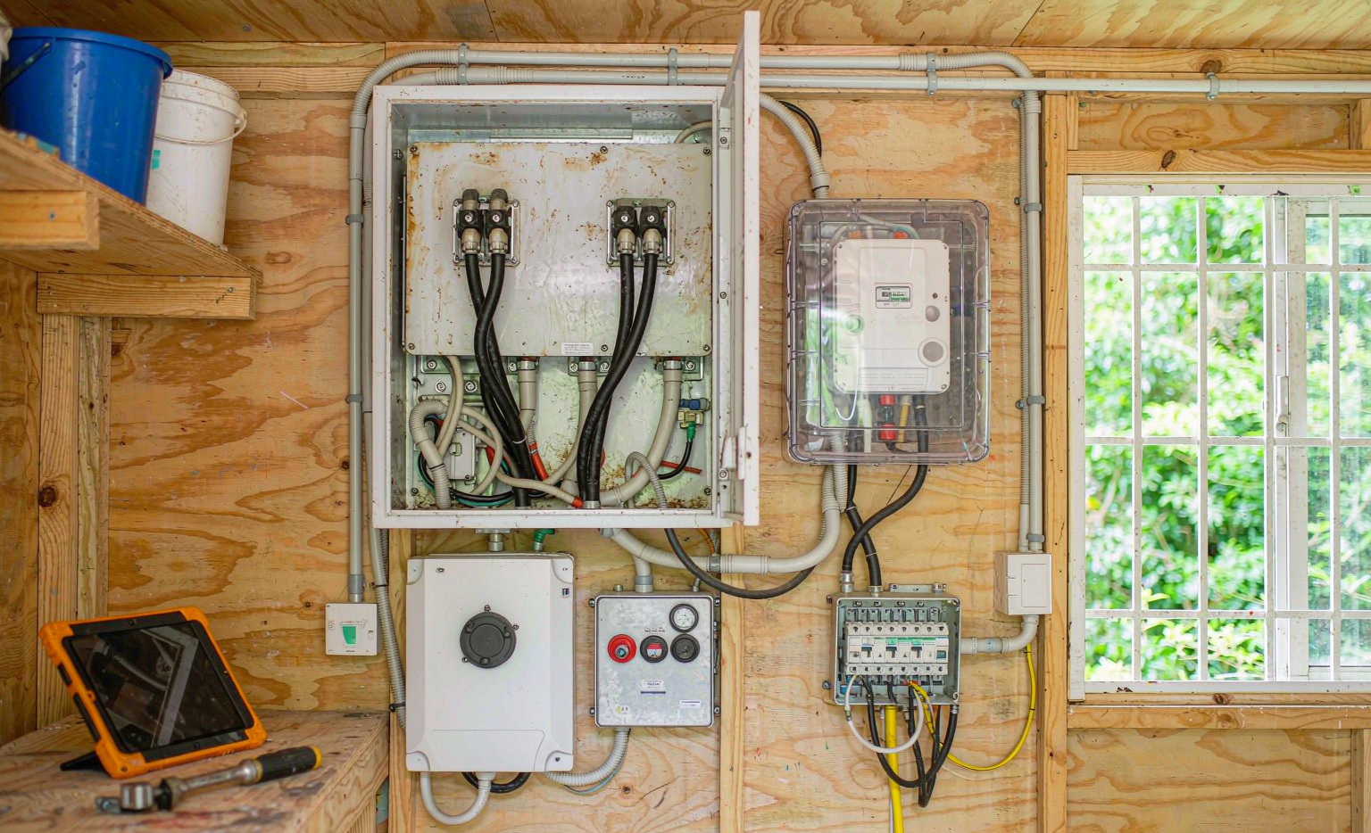
The single most valuable thing you can do during integration is install a separate critical loads subpanel and move only the circuits you genuinely need onto it. Backing up the entire panel is the decision that forces a 12 kW inverter and a 20 kWh battery onto a cabin that would have been perfectly happy with 5 kW and 10 kWh.
On the critical loads panel I put: lighting, refrigerator, well pump (with a soft starter), internet and communications, the septic or treatment system, and one general-purpose receptacle circuit. On the main panel I leave: resistance water heating, electric ranges, clothes dryers, and any workshop equipment with large motors. Then I use the low-SoC logic of the system to shed loads automatically — a contactor or smart breaker that drops the mini-split below 30 % SoC and drops the well pump below 20 %, so the cabin keeps lights and refrigeration through the last night of a bad weather window.
The soft starter on the well pump deserves special mention because it is the highest-return item in the whole integration. A submersible pump with a 5× locked-rotor surge drops to roughly 2× with a soft starter, which typically takes a 4.5 kW surge to 1.8–2.0 kW. That can be the difference between needing an 8 kW inverter and a 5 kW one.
The Neutral Bond Problem
Here is the failure I see most often, and it is almost invisible until someone gets a tingle off an appliance chassis or the GFCIs trip randomly. A system has exactly one neutral-to-ground bond. When the cabin is running off-grid, the inverter/charger becomes a separately derived source and must make that bond, usually with an internal relay. When the generator or the utility is feeding the panel, that bond now lives at the generator or the service, and the inverter’s internal relay must open.
Get this wrong and you have a second bond in parallel with the first. Return current divides between the neutral and the equipment ground, objectionable current flows on grounding conductors and metal parts in violation of NEC 250.6, GFCI and AFCI devices see the imbalance and nuisance-trip, and the ground-fault detection you were relying on is compromised. The practical rules I follow:
- Transfer switches in an off-grid system must switch the neutral (a 3-pole or switched-neutral ATS) whenever the sources have different bonding arrangements.
- Set the inverter’s bonding mode explicitly in firmware and verify it with a meter, don’t assume the factory default.
- If the generator has a bonded neutral (most portable generators ship this way), either remove that bond and let the inverter do it, or use a switched-neutral transfer switch that prevents the two bonds from ever being in parallel.
Generator Integration: Size It, Then Teach It Good Manners
A generator in a cabin system has two jobs: supply the loads and charge the battery, usually at the same time. Sizing it for both is the step people skip. If your loads peak at 5 kW and you want 60 A of charging at 51.2 V, that is about 3.1 kW DC, or roughly 3.4 kW AC after charger losses. Together that is 8.4 kW of continuous demand, so a 7 kW genset will brown out and a 10–12 kW unit will sit at a comfortable 70–85 % load. I then program the inverter’s AC input current limit to about 80 % of the generator’s continuous rating, so a load spike steals from charging instead of stalling the genset.
Diesel and propane sets have a fuel curve, and it is not linear. Efficiency in kWh per litre peaks in the 60–80 % load band and falls off badly below about 30 %. This drives a simple but very effective charging strategy: run the generator hard to bring the pack from 20 % to 80–90 % at full charger current, then shut down and let solar finish the last 10–20 %. Pushing that final fraction with the generator means running at a low current where you are burning fuel mostly to make waste heat. I set the auto-start trigger at 20–25 % SoC or 3.05 V/cell under load, with a 30–60 minute confirmation delay so a passing cloud or a single microwave cycle doesn’t fire the genset, plus a 30–45 minute minimum run time.
The minimum run time is not arbitrary — it protects the generator. Short-cycling a diesel causes wet stacking, where unburned fuel and soot accumulate in the exhaust, and it never reaches the temperature that boils condensation out of the oil. I also set a monthly exercise cycle of 20–30 minutes under at least 50 % load, ideally into the battery so the run is doing useful work.
One more compatibility check that catches a lot of field failures: inverter/chargers are picky about generator power quality. Many will refuse to sync if voltage THD exceeds roughly 12–15 % or if frequency wanders outside ±3–5 Hz. Standard synchronous portable generators often sit at 8–15 % THD; inverter generators deliver under 5 %. If a customer already owns a conventional genset, I measure its THD and frequency stability under load before promising that it will work.
Grounding, Bonding, and Surge Protection at Remote Sites
Cabins are commonly sited on exactly the terrain that makes grounding hard and lightning likely — ridges, exposed lakefront, thin rocky soil. Both problems need to be designed for, not discovered.
On the grounding electrode, NEC 250.53 wants a resistance to earth of 25 Ω or less for a single rod, or two rods at least 6 ft apart. In rocky or sandy soil you will not get there with a driven rod, and the honest answers are a ground ring, a chemically enhanced electrode, or a concrete-encased electrode (Ufer) tied into the foundation. I test with a three-point fall-of-potential method and record the number, because “it has a ground rod” is not the same as “it has a working ground.”
Surge protection is where I spend money on remote installations. A single Type 1 or Type 2 SPD at the service entrance is the baseline (UL 1449 4th edition, with a nominal discharge rating of 20 kA or better for exposed sites). I add a Type 2 device at the critical loads subpanel and a dedicated DC SPD at the array. But the thing that actually determines whether an SPD works is lead length, and this is the detail that gets ignored: at 20 kA on an 8/20 µs waveform, every inch of lead contributes on the order of 15–20 V to the let-through voltage. A device with a 700 V clamping rating mounted with 12 inches of total lead delivers well over 900 V at the equipment. Keep the total lead length under about 12 inches (300 mm) and twist the conductors.
Finally, protect the data lines. In my experience the component most often killed by an induced surge is not the inverter — it survives because it is on a protected bus — but the BMS communication port, the RS485 run to the charge controller, or the Ethernet cable to the satellite modem. Any conductor that leaves the building needs a listed data-line protector at both ends.
Cold-Climate Integration: The Chemistry Sets the Rules
Every winter failure I have been called to diagnose came down to someone asking LFP to accept charge when it was too cold to do so safely. Below 0 °C, lithium plates onto the anode surface instead of intercalating into it, and that plated lithium is both a permanent capacity loss and, if it grows dendrites, a safety problem. My standard BMS configuration is zero charge current at 0 °C, resuming at +3 to +5 °C with hysteresis so the contactor does not chatter at the threshold. Discharge is much more forgiving — typically allowed down to −20 °C — but you must respect the reduced capability.
Capacity at −10 °C for LFP is roughly 80–85 % of rated, and at −20 °C around 70–75 %. Internal resistance roughly doubles to quadruples over that range, which means the pack sags hard under load and hits the low-voltage cut long before the energy is actually gone. A cabin that ran fine in October will trip offline in January on a pack that still has 20 % left in it.
There are two integration answers. The first is heat: a thermostat-controlled pad in the 150–600 W range inside an insulated enclosure. Insulation is the part people skip and it is the cheapest energy you will ever spend — a well-sealed box with 50–100 mm of PIR and R-10 walls will hold 10–20 K above ambient on 100–200 W. A bare 300 W pad in an uninsulated shed burns 2.4 kWh in eight hours, which on a small off-grid system is a real tax.
The second answer is a different chemistry. This is the one place where I will steer a cabin customer toward a sodium-ion battery pack: at −20 °C a well-built sodium-ion cell retains roughly 85–90 % of its room-temperature capacity and, critically, will accept 0.2–0.3C charge without any heater at all. For an unheated cabin that is occupied only at weekends, deleting the heater pad, its thermostat, and its standby drain can be the difference between a system that works and one that needs a generator run every visit.
On the solar side, remember that cold raises open-circuit voltage. Crystalline modules have a Voc temperature coefficient of about −0.25 to −0.35 %/°C, so a string with an STC Voc of 450 V at −30 °C will present roughly 15–20 % more, or 520–540 V. Design the string using the NEC 690.7(A) correction factor for the site’s record low (roughly 1.17–1.25 for −20 to −40 °C), and confirm the result against both the charge controller’s maximum input and the 600 V DC wiring limit. This calculation is what prevents a cold, clear, −25 °C morning from destroying a controller.
DC Cabling: The Unforgiving Arithmetic of 48 V
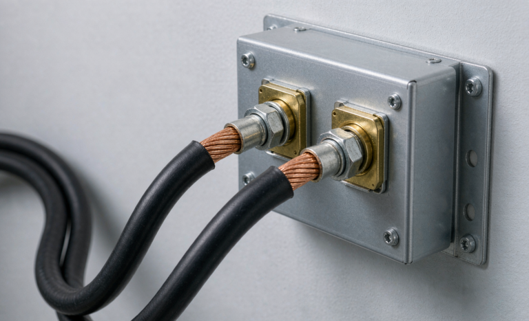
At 48 V, current is high and mistakes are thermal. A 12 kW inverter on a 48 V bus draws about 250 A. Hold the DC voltage drop to 3 % or less and you will discover that cable length, not cross-section, is your real constraint: at 250 A you are looking at 4/0 AWG (about 120 mm²) and still only a couple of metres of run. The integration rule I enforce is simple — put the battery and the inverter within 2–3 m of each other and design the room around that, rather than designing the room and then buying cable.
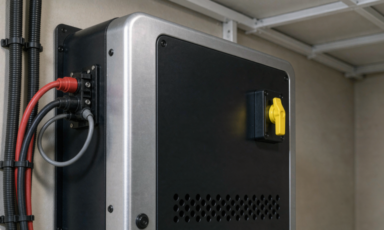
Terminations matter as much as conductor size. I specify calibrated hexagonal crimps, a pull test on the first article of every run, and torque to the lug manufacturer’s figure — commonly 8–12 N·m for M6 and 12–16 N·m for M8 — with a torque stripe so a later inspection can see whether a lug has moved. Then re-torque after the first 50 hours of operation and annually after that. Loosening terminations are the most common cause of the melted lugs I get sent photographs of.
The other non-negotiable is precharge. A 5 kW inverter can present 5–20 mF of DC-link capacitance, and closing a contactor into a discharged capacitor bank is a genuine arc-welding event. With a 20 Ω precharge resistor on a 10 mF input at 51.2 V, peak current is about 2.6 A, the time constant is 0.2 s, and the bank reaches full charge in roughly 1 s. Cheap, and it saves contactors, fuses, and occasionally fingers.
Commissioning: The Sequence That Prevents the Return Trip
On a remote site, a callback costs a full day. I would rather spend two hours on a disciplined commissioning sequence than gamble on a four-hour round trip in February. Before energising anything:
- Megger the DC bus at 500 V DC. The code floor for a 48 V system is trivially low, but I reject anything under 1 MΩ — a healthy pack reads in the tens of MΩ.
- Check cell balance at 40–60 % SoC. A spread greater than 30 mV on a new pack is a reject; on a pack that has been in service, more than 50 mV and rising is a diagnostic, not a nuisance.
- Verify every BMS setpoint against the cell datasheet: overvoltage 3.65 V ±25 mV, undervoltage 2.50 V, charge-temperature cutoffs, continuous and peak current limits, short-circuit lockout.
- Confirm correct polarity, then precharge before closing.
Then the functional sequence, under load and in this order:
- Full-load test at 100 % of continuous rating for 30 minutes.
- Surge test — start the well pump and the mini-split compressor, three times, and log the minimum DC bus voltage.
- Generator transfer test, three times, measuring transfer time and confirming no load reboots.
- Generator charging test at full programmed current, confirming the AC input limit holds and the genset does not bog.
- Low-SoC load-shed test — drive the pack down and confirm the shed relays fire at the right setpoints.
- PV curtailment test, for AC-coupled systems: full sun, low load, high SoC, and confirm the grid-tie inverter actually backs off.
- Thermal scan after 2–4 hours above 50 % load. Any termination more than 20 K above ambient gets investigated, and more than 30 K gets shut down.
Close it out with a commissioning pack: single-line diagram, torque log, the full setpoint sheet, the insulation and cell-balance readings, and a spare fuse list. When a customer calls me three years later with an odd reading, that pack is the difference between a five-minute phone call and a site visit.
Frequently Asked Questions
Can I add storage to my cabin’s existing grid-tie solar array?
Yes, through AC coupling, but only if the battery inverter is explicitly rated for it. The battery inverter must be able to regulate an AC bus that your existing grid-tie inverter is also driving, and it does that by shifting its output frequency to signal curtailment. Keep the PV inverter’s AC nameplate within the manufacturer’s published AC-coupling ratio — usually 1.0–1.5× the battery inverter’s continuous rating. Also confirm your grid-tie inverter will run at all without a stable grid: many require a grid-forming source, which your battery inverter becomes when off-grid.
Do I really need a separate critical loads panel?
You do not strictly need one, but you will pay for not having one. Backing up the whole panel means sizing the inverter and battery for your largest loads — typically resistance water heating or a workshop tool — that run for minutes a year. A critical loads panel of six to eight circuits usually cuts the required inverter rating by a third to a half, and that saving pays for the panel several times over.
Can I keep the generator I already own?
Often yes, but verify two things first. Measure its output voltage THD under load and its frequency stability; many inverter/chargers will refuse to sync above roughly 12–15 % THD or outside ±3–5 Hz, and conventional portable generators frequently sit at 8–15 % THD while inverter generators stay under 5 %. Second, find and document its neutral bonding arrangement, because that determines whether you need a switched-neutral transfer switch.
48 V or a high-voltage stack for a cabin?
For most cabins, 48 V. High-voltage stacks (roughly 200–400 V nominal) reduce current and let you use much lighter cable, but they need qualified personnel, have stricter service clearances, and are harder to expand one module at a time. Below about 15 kW of inverter capacity and 30 kWh of storage, 48 V remains simpler, cheaper to service, and far easier to find replacement parts for in a small town.
Will the battery work in a freezing cabin with no heat?
It will discharge, down to about −20 °C for LFP, but with 70–85 % of its rated capacity and much higher internal resistance. It will not safely accept charge below 0 °C, and a good BMS will not let you try. If the cabin is unheated between visits, either fit an insulated enclosure with a thermostat-controlled pad, or specify a sodium-ion chemistry that will take charge at −20 °C without heating.
How large an inverter do I need for a well pump?
Do not size for the running watts — a ½ hp pump runs at 750–1000 W but can demand 3–5 kW for one to three seconds on start. Check the nameplate LRA or FLA, then specify an inverter whose 3-second surge rating exceeds it with margin. In practice, fitting a soft starter first usually cuts that surge by 60–70 % and lets you buy an inverter one size smaller.
Can I expand the battery later, or mix old and new modules?
Expanding is fine if you planned the busbar, fusing, and enclosure space for it. Mixing modules of different ages is where it goes wrong: the new module’s lower internal resistance means it takes and gives more current, and the pack’s usable capacity is capped by the weakest module. If you must mix, match chemistry and capacity, keep the state-of-health difference small, re-baseline the BMS capacity figure, and expect the older module to set the performance.
Does an off-grid cabin installation need a permit and inspection?
Almost always yes, and it is worth wanting it. Even fully off-grid, most jurisdictions require a building or electrical permit, and the applicable codes — NEC Article 706 for energy storage, 690 for PV, 705 for interconnection, and 710 for microgrids — exist because the failure modes are real. NFPA 855 governs ESS installation and separation. An inspected installation also protects your insurance position, which matters a great deal for a structure that burns down with nobody there to notice for a week.