Home Energy Storage Battery Cable Sizing and Voltage Drop
I have audited more than 200 residential battery installs over the past decade, and the single most common reason a home energy storage system underperforms is not the cells. It is the cable between the battery and everything else. Undersized conductors, loose lugs, and ignored voltage drop turn a healthy lithium battery into a system that trips its inverter at the worst moment or quietly cooks a connection until it fails. My name is Karl Huang, Senior Lithium Battery Engineer, and in this article I will walk through the exact cable sizing and voltage drop math I use before a single terminal is torqued.
Why Cable Sizing Decides Whether Your Home Battery Actually Works
A home energy storage battery does not live in isolation. It connects to an inverter, a busbar, a backup load panel, and often a solar charge controller. Every one of those connections is a length of copper with a fixed resistance. At 48 V nominal, a lithium battery can deliver 100 A or more to a whole-home inverter during a grid outage. That current multiplied by cable resistance produces heat and a voltage drop that the inverter sees as a sagging bus.
If the cable is too small, two things happen. First, the conductor warms above its rating, which accelerates insulation aging and can melt a lug. Second, the voltage at the inverter terminals falls below its under-voltage trip point even though the battery itself is still full. I have seen a 13.5 kWh system fail to start a well pump simply because a 20 foot run was wired with 6 AWG instead of 2 AWG. The cells were fine. The cable was the bottleneck.
The Voltage Drop Math Every Installer Should Run First
Voltage drop is not mysterious. For a DC battery circuit the one-way formula is Vd = (2 x K x I x L) / CM, where K is the copper constant 12.9 at 75 degrees Celsius, I is current in amperes, L is the one-way length in feet, and CM is the conductor circular mil area. The factor of 2 accounts for the current traveling out and back.
As a field rule I keep total voltage drop under 3 percent on the battery to inverter run. On a 48 V system that is about 1.44 V of allowed loss. A 100 A load over 25 feet with 2 AWG copper (66,360 CM) gives Vd = (2 x 12.9 x 100 x 25) / 66360 = 0.97 V, or roughly 2 percent. That passes. The same run with 4 AWG (41,740 CM) gives 1.55 V, or 3.2 percent, which I would reject for a whole-home backup circuit.
Do not forget that voltage drop scales with both current and distance. A cable that is perfect for a 30 A solar combiner can be dangerously lossy at 120 A inverter surge. Always size for the worst-case continuous current plus the documented surge, not the battery nameplate average.
Ampacity, Conductor Size, and NEC 706 Derating
In the United States the relevant code path is NEC Article 706 for Energy Storage Systems, supported by Article 310 for conductor ampacity and Article 625 for related power circuits. Conductor ampacity comes from NEC Table 310.16. As a quick reference, 2 AWG copper is rated about 115 A at 75 degrees Celsius, 1 AWG about 130 A, 1/0 about 150 A, 2/0 about 175 A, 3/0 about 200 A, and 4/0 about 230 A using 75 degree Celsius termination columns.
Two derating steps matter. If your termination is rated 75 degrees Celsius, you must use the 75 degree column even when the cable is marked 90 degrees. And when ambient temperature exceeds 30 degrees Celsius, or more than three current-carrying conductors are bundled, the allowable ampacity drops. I have watched a neatly zip-tied bundle of battery cables in a hot garage lose 20 percent of its rating simply from heat buildup. Spread the conductors or step up a size.
For a typical 48 V home energy storage system feeding a 5 kW continuous inverter, plan for roughly 105 A at the low end of the state of charge. That already pushes you to 1/0 or 2/0 for any run longer than a few feet. Do not size to the inverter’s continuous number and hope. Size to surge.
Choosing the Right Cable Type for a Home Energy Storage System
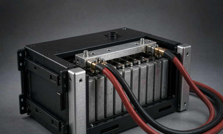
Most residential battery banks use flexible stranded copper, often welding cable or fine-stranded UL 1426 battery cable, because the terminations see vibration and thermal cycling. I prefer tinned copper in coastal or high-humidity homes; the tin layer slows the creep corrosion that eventually makes a lug read open under load.
Solid building wire works inside a panel but is brittle at battery terminals that flex during thermal expansion. For the exposed run between a wall-mounted lithium battery module and the inverter, use listed flexible battery cable with an insulation rated for at least 75 degrees Celsius and, ideally, 105 degrees for the proximity to enclosures.
Grounding deserves its own mention. The equipment grounding conductor must follow NEC 250.122 sizing and bond the battery enclosure, inverter chassis, and the backup panel to a single grounding electrode system. A floating home energy storage battery is a shock hazard waiting for the first fault.
Fusing, Lugs, and Torque: The Failure Points I See in Audits
A conductor is only as safe as the overcurrent device protecting it. Between the battery and the inverter I specify a fuse rated just above the maximum continuous current but well below the cable ampacity. For inverter feeds, a Class T or MRBF fuse in a listed holder is my default because it clears fast enough to protect the cable during a short.
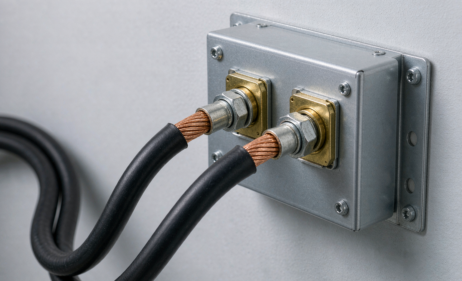
Lugs are where audits fail. A crimp that looks tight can have 40 percent contact area, and that hidden resistance becomes a heater. I use UL listed lugs matched to the cable, a proper hydraulic crimper, and a torque wrench set to the lug manufacturer’s spec, commonly 18 to 28 N-m for 2/0 terminations. Then I proof-load the connection and re-torque after the first thermal cycle. Anti-oxidant compound on aluminum transitions, and a dab on copper threads, prevents the galvanic creep that loosens joints over a year.
Shunt placement for the battery management system also matters. Put the current shunt on the negative main so the BMS reads true pack current, and keep sense wires away from the high-current path to avoid induced error. A misplaced shunt tells the system it is at half capacity and forces needless disconnects.
A Worked Example From a Real 48 V Retrofit
Last winter I sized a retrofit for a 14 kWh wall-mounted lithium battery serving a 6 kW inverter in a detached garage 18 feet from the main panel. Continuous draw at low state of charge was 125 A with a 180 A surge. The 3 percent rule on 48 V allowed 1.44 V.
Working the formula backward, CM = (2 x 12.9 x 125 x 18) / 1.44 = 64,062 circular mils. That put us between 2 AWG and 1 AWG. Because ambient in that garage reaches 38 degrees Celsius in summer, I applied the temperature correction and stepped up to 1/0 (105,600 CM) for margin. Final measured drop at 125 A was 0.87 V, about 1.8 percent. The inverter has not tripped once through two storm outages.
That example is the whole point. Cable sizing is not a guess corrected after a failure. It is arithmetic you do on paper before the wall plate goes up.
Frequently Asked Questions
How do I size battery cables for a home energy storage system?
Start from the worst-case continuous current plus surge, pick a target voltage drop of 3 percent or less, and solve Vd = (2 x K x I x L) / CM for the circular mil area. Then confirm the chosen AWG meets NEC 706 ampacity after temperature and bundling derating. Always select the cable for the surge current, not the average load.
What voltage drop is acceptable for home battery wiring?
I keep the battery to inverter run at or below 3 percent total drop, which is about 1.44 V on a 48 V nominal system. Some designers allow up to 5 percent, but for a home energy storage battery feeding an inverter with tight under-voltage trip points, 3 percent leaves the safest margin.
Can I use copper or should I use aluminum for home energy storage cables?
For the battery to inverter jumpers I use copper because it carries more current in a smaller strand bundle and resists the corrosion that loosens terminations. Aluminum is acceptable for larger service feeders when terminated in listed Al-rated lugs with anti-oxidant, but I avoid it at the high-cycle battery terminals themselves.
What AWG do I need for a 48 V 100 A home battery connection?
For a short 5 foot run, 2 AWG copper is adequate at roughly 115 A ampacity. For any run beyond 15 feet at 100 A, step up to 1/0 or 2/0 to keep drop under 3 percent. Always verify against the actual one-way length, not the catalog worst case.
Does cable length affect my home energy storage inverter trip points?
Yes. Longer cable means more resistance, which means more voltage drop under load. If the drop at the inverter terminals falls below its under-voltage setting while the battery is still charged, the inverter trips unnecessarily. Proper sizing keeps the bus voltage inside the inverter’s operating window even at peak current.
Are UL listed lugs required for home energy storage battery banks?
In a compliant install, yes. The lug, crimp, and holder must be listed for the cable and current, properly torqued, and protected by a fuse sized below the conductor ampacity. Unlisted hardware is the fastest route to a high-resistance joint that heats, arcs, and fails the next inspection.
Further Reading
References