Lithium Battery Deployment for Solar Kits
I have commissioned lithium battery packs for off-grid solar kits on three continents — rural clinics, telecom huts, farm outbuildings and a fair number of weekend cabins. The pattern is always the same. The cells almost never fail. What fails is everything around them: an undersized cable that drops two volts at surge, a charge controller still running the lead-acid profile it shipped with, a sealed enclosure that sits at 65 °C every afternoon in July, or a pack that was charged at −6 °C once and quietly lost a third of its cycle life.
A solar kit is a specific product form: panels, a charge controller, a battery, usually an inverter, all shipped together and installed by someone who is not an electrician. That single constraint changes the engineering. Nobody comes back in six months to re-torque a terminal or re-flash a controller. The commissioning window is one afternoon, and whatever shortcuts survive that afternoon get repaid over the next ten years. This guide is the field sequence I use, written for the person actually standing in front of the kit with a torque wrench in one hand and a multimeter in the other.
Why a Solar Kit Is Not a Scaled-Down Rack System
The instinct is to treat a 5 kWh solar kit as a miniature version of a 500 kWh container. It is not, and the differences are not cosmetic.
- The installer is not a specialist. A utility-scale project has commissioning engineers, a written acceptance test and a service contract. A solar kit has one person, one afternoon, and a translated quick-start card. Every design choice that assumes skilled intervention is a latent defect.
- It ships as a battery, then lives as an appliance. Transport classification (UN 3481 for a battery packed with or contained in equipment) governs the first week. Thermal and cycling behaviour governs the next decade. Both have to be designed in.
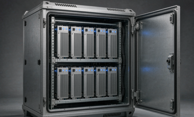
- The enclosure is small and often sealed. A rack has fan trays and aisle airflow. A kit enclosure is a box the size of a suitcase, frequently outdoors, sometimes in direct sun. Heat has nowhere to go, and heat is what ages a lithium ion battery fastest.
- The load profile is peaky. A cabinet runs a pump for thirty seconds and a modem for twenty-four hours. The energy number is easy; the peak power number is where kits get mis-sized.
So the deployment sequence below is deliberately ordered: load, chemistry, energy and power, charge control, wiring, thermal, commissioning, compliance, and finally the point at which a catalogue kit stops being the right answer.
Step 1: Build the Load List Before You Look at the Panels
Every solar kit I have seen under-perform started with the panel rating. “I have 800 W of panels, what battery do I need?” is an unanswerable question. The right first artefact is a load list with three columns per load: average watts, hours per day, and peak or surge watts.
Here is a real one from a small off-grid cabin specification I reviewed:
- LED lighting: 60 W × 5 h = 300 Wh
- Refrigerator (inverter-driven, averaged): 45 W × 24 h = 1080 Wh
- Water pump, ½ hp: 500 W running × 0.5 h = 250 Wh, but 1500 W starting surge
- Laptop and small electronics: 60 W × 4 h = 240 Wh
- Router and monitoring: 15 W × 24 h = 360 Wh
AC-side daily energy: 2230 Wh. Now convert to DC energy by dividing through inverter efficiency — 0.88 is a honest figure for a small inverter at partial load — giving 2534 Wh drawn from the pack.
Next, autonomy. Two days of no sun is the default I specify for anything habitable; one day is acceptable for telemetry loads with a generator backup. Two days: 5068 Wh. Divide by usable depth of discharge — 0.90 is realistic for LiFePO4 — giving 5631 Wh. Then apply a 1.15 margin for cold-weather capacity loss and end-of-life fade: roughly 6.5 kWh of nameplate capacity. In practice that is two 48 V 100 Ah modules, or a single 48 V 150 Ah module if the geometry allows it.
Note what did not appear in that arithmetic: the panel rating. Panels determine how fast the pack refills; they do not determine how big it is.
Step 2: Chemistry — Why LFP Is the Default for Solar Kits
For a stationary solar kit, an LFP battery is the correct default, and the reasoning has nothing to do with fashion.
- Cycle life. LiFePO4 delivers 3000–6000 cycles to 80% capacity at 0.5C and 25 °C. An NCM battery of comparable quality delivers 800–1500. A solar kit cycles daily; that difference is the difference between a ten-year asset and a four-year one.
- Thermal behaviour. LFP onset of thermal runaway sits around 270 °C versus roughly 150–200 °C for nickel-rich chemistries. In an unattended box in a hot climate, that margin is the product.
- Voltage compatibility. Four LFP cells in series give 12.8 V nominal, which sits comfortably inside the operating window of 12 V equipment designed for lead-acid. A 12v lithium battery in a drop-in form factor is usually 4S LFP for exactly this reason.
The trade-offs are real and they are worth knowing before you buy. LFP has lower energy density — roughly 90–160 Wh/kg against 160–260 Wh/kg for NCM — so a backpack-portable kit is one of the few places NCM still earns its keep. LFP’s open-circuit voltage curve is also famously flat between 20% and 90% state of charge, which means voltage tells you almost nothing about SOC and the system must rely on coulomb counting. And LFP will not accept charge below 0 °C without plating lithium metal onto the anode; more on that in the thermal section.
Step 3: Energy and Power Are Two Different Numbers
This is the most common sizing error in solar kits: the energy number is right and the power number is wrong. The pack holds enough watt-hours, but when the pump kicks in the terminal voltage sags far enough to trip the BMS undervoltage protection, and the whole kit drops out.
Take the 1500 W pump surge from our load list. Through a 0.88-efficient inverter that is 1705 W from the pack. Now run it at two system voltages, using 46 V and 11.5 V as realistic sag-inclusive values:
- 48 V system: 1705 / 46 = 37 A. A 100 Ah LFP module rated for 1C continuous handles this with room to spare.
- 12 V system: 1705 / 11.5 = 148 A, and brief starting transients push past 200 A. That is a 2C discharge on a 100 Ah pack, plus a cable and termination design that most kits are not built for.
My rule: any solar kit with a continuous inverter above about 2 kW should be 48 V. Below 1 kW, 12 V is fine and much simpler to source. Between the two, look at your peak surge and the cable run length before deciding.
On the charging side, solar arrays are gentle. Real array output is roughly 75% of STC nameplate once you account for cell temperature, dust, mismatch and wiring. So a 5.12 kWh 48 V pack charged at a healthy 0.2C wants about 20 A, or 1024 W at the pack terminals — meaning roughly 1370 W of STC array. Go much above 0.5C of array and you are spending money on panels the battery cannot absorb.
One seasonal correction that catches people out: in winter at high latitude, peak sun hours may collapse from 5.5 to 2.5. The fix is more array, not more battery. Adding battery capacity to a winter-starved site just gives you a larger pack that never reaches full charge, and LFP that lives at partial state of charge without periodic full charges drifts badly in its SOC estimate.
Step 4: Charge Control — The Lead-Acid Defaults That Destroy Lithium Packs
If I could change one thing about every solar kit shipped, it would be the charge controller default profile. Controllers leave the factory set for sealed lead-acid, and nobody changes it.
Here is what a lead-acid profile does to a lithium battery pack, and the values I use instead for a 12.8 V (4S) LFP pack:
- Absorption / bulk voltage: lead-acid wants 14.4–14.8 V. LFP wants 14.2–14.6 V. Not dramatically different, but the top of the lead-acid range holds the pack at a stressfully high voltage for hours.
- Float: lead-acid floats at 13.5–13.8 V indefinitely. LFP should float at 13.5–13.6 V, or better, float not at all. Holding LFP at 100% SOC in a hot enclosure is a calendar-aging accelerator.
- Equalisation: this is the killer. Lead-acid equalisation pushes 15.5–16.0 V through the pack for hours. LFP does not need it. On a 4S pack that is 3.9 V per cell, well past the point where you are driving electrolyte oxidation and accelerating impedance growth. Turn equalisation off.
- Temperature compensation: lead-acid controllers apply about −3 mV/°C per cell, which at −10 °C raises charge voltage. On a lithium pack, low temperature calls for no charge at all, not a higher voltage. Disable compensation and let the BMS enforce the low-temperature cut-off.
- Absorption time: drop the lead-acid habit of a fixed two-to-four-hour absorption stage. LFP reaches its CV target and current decays naturally; terminate on tail current at about 0.05C and move on.
A concrete failure I was asked to diagnose: a 12.8 V 200 Ah kit in a service van, controller left on the factory sealed-lead-acid profile with monthly equalisation enabled. Cabin temperatures in summer reached 60 °C. After fourteen months the pack measured 82% of rated capacity and DCIR had risen about 40% from its commissioning baseline. The cells were not defective. They were equalised once a month in an oven.
One more setting that belongs here: the inverter’s low-voltage disconnect. Lead-acid practice is 10.5 V on a 12 V system. On LFP, the BMS will typically open at around 2.5 V per cell (10.0 V for a 12.8 V pack), so an inverter set to 10.5 V will chatter on and off against the BMS the whole way down, and then hard-disconnect the pack with no warning. Set the inverter disconnect to 12.0–12.4 V so it shuts down gracefully well before the BMS intervenes.
Step 5: Wiring, Fusing and Voltage Drop
Most solar kit field failures I attend are wiring failures reported as battery failures. Three items matter.
Voltage Drop
Budget 2–3% total drop across the whole DC path, and remember the path length is there-and-back. For a 10 m round trip at 100 A on a 12 V system, staying under 3% (0.36 V) requires roughly 35 mm² (2 AWG) copper — expensive, stiff and hard to terminate correctly in the field. The same power at 48 V (25 A) needs about 6 mm². This is the second, independent reason large kits belong at 48 V.
Torque
Every bolted joint is a consumable. Torque the terminals to the manufacturer’s specification with a calibrated wrench, mark each fastener with a torque stripe, and re-check after the first thermal cycle. Loose high-current terminals do not fail politely; they heat, oxidise, heat further, and eventually cook the enclosure. In my own service data, connectors and harnesses account for roughly 45–55% of “dead battery” service calls, while cells account for less than a third.
Overcurrent Protection and Fault Current
This is where lead-acid intuition is actively dangerous. LFP cells have very low internal resistance, so a 48 V 100 Ah module can deliver several thousand amps into a dead short — I have measured 3000–8000 A depending on cell format and state of charge. Automotive blade fuses and small DC breakers rated at 1000 A interrupting capacity simply will not clear that fault; the fuse becomes the ignition source. Specify Class T or NH fuses with interrupting ratings of 20 kA or better, or MRBF fuses at the terminal where the fault current is limited by the cable impedance. Size the fuse to protect the cable, not the load.
Finally, pre-charge. Inverter DC-link capacitors are large and empty. Closing a contactor into them produces a current spike that welds contacts and can trip the BMS short-circuit protection instantly. Use a 100 Ω / 10 W resistor across the contact for a few seconds to bring the caps up, then close. Every large kit should ship with that resistor and an instruction to use it.
Step 6: The Thermal Envelope — The Quiet Life-Shortener
Calendar ageing of a lithium ion battery follows an Arrhenius relationship, and the practical rule of thumb is brutally simple: every 10 K increase in cell temperature roughly halves the time to end of life. In a sealed outdoor enclosure in summer, cell temperature of 55–65 °C is entirely achievable even when ambient is 30 °C. Compared to a cell living at 25 °C, that is somewhere between a threefold and eightfold acceleration.
What I specify:
- Site the pack in shade, on the coolest available wall, and never directly above or beside the inverter’s heat sink.
- Light-coloured, vented enclosures. A white or light-grey enclosure with filtered high and low vents can run 10–15 K cooler than a dark sealed box of identical size.
- Do not seal it. Sealed enclosures protect against dust and defeat everything else. Passive convection costs nothing.
- Cold-climate kits need self-heating. Below 0 °C, charging must stop. For a site that sees −20 °C, specify a pack with integrated PTC heating film (typically 30–80 W) and make sure the heating is powered from the array side, not from the pack it is trying to warm.
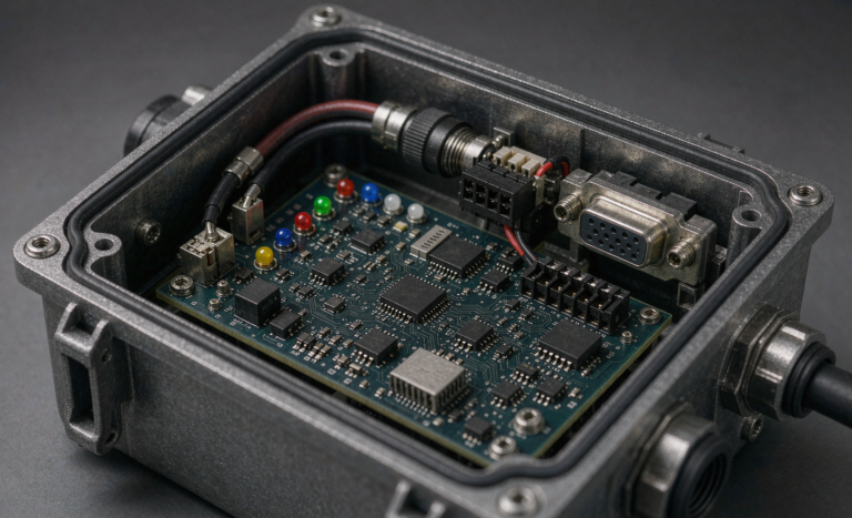
- Redundant low-temperature cut-off. Do not rely on the BMS alone. Fit the controller’s temperature sensor to the pack as well, so charging stops at source rather than the BMS opening under load and dumping the array.
Step 7: Commissioning — The Seven Checks Before You Walk Away
Assume you will never return. Do these, write down the numbers, and store the raw traces rather than just the pass/fail summary.
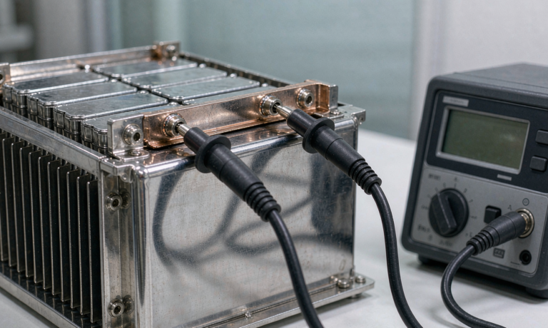
- Torque every joint with a calibrated wrench to specification, apply a torque stripe, and photograph the terminals.
- Verify polarity, then pre-charge the inverter DC link through a resistor before closing the main contactor.
- Measure each module’s open-circuit voltage and compare against the shipping document. Any module more than about 100 mV low on a 48 V stack gets isolated and queried before it is paralleled.
- Insulation test before paralleling. 500 V megohmmeter, string by string, expecting more than 1 MΩ. Once strings are paralleled you only get a system-level reading that hides the single bad string.
- Capacity test. Full charge, rest two hours, then constant-current discharge at 0.2C to the inverter’s cut-off. A healthy new LFP kit delivers 95–100% of nameplate. Below 90%, stop and call the supplier — do not “let it break in.”
- Reset the SOC gauge. Coulomb counters drift a few percent per month. A full charge, two-hour rest and known discharge teaches the gauge where full and empty actually are.
- Load test under the real peak. Run every load simultaneously, then switch the largest motor on and off three times. Record the minimum bus voltage and recovery time. If the pack sags into the BMS undervoltage region, you have found the sizing error on day one instead of on the first cold morning.
Hand over the commissioning report, the torque schedule, the load list and a first-annual-inspection date. The single most useful document in year three is the set of numbers from day one.
Step 8: Compliance and Transport
Solar kits ship as batteries, and the paperwork is not optional.
- UN 38.3 test summary has been mandatory to supply since 2020. Ask for it before you buy, not after a shipment is held.
- UN 3480 covers batteries shipped alone; UN 3481 covers batteries packed with or contained in equipment — which is what most solar kits are. Air freight under IATA rules requires state of charge at or below 30%.
- IEC 62133-2 is the baseline safety standard for portable sealed cells and batteries. IEC 62619 covers industrial and stationary storage applications. UL 1973 and, for fixed installations in North America, UL 9540 with UL 9540A thermal propagation test data, are what most authorities having jurisdiction will actually ask to see.
- CE / UKCA marking for the relevant markets, with a declaration of conformity you can read.
The documents that should travel with the goods: UN 38.3 test summary, safety data sheet, state-of-charge declaration for transport, and the commissioning report template. If a supplier cannot produce the first two within a day, that tells you what you need to know about their test regime.
Step 9: When a Catalogue Kit Stops Being the Right Answer
Off-the-shelf solar kits cover maybe eighty per cent of applications, and they should be your first choice: they are certified, stocked, and cheap. A custom battery solution earns its premium when one of these is true:
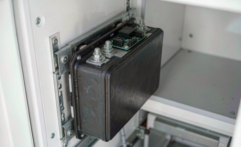
- Geometry is dictated by the installation. Under a van seat, in a boat bilge, in a rack with 40 mm of spare height. When the enclosure is the constraint, a standard module is simply the wrong shape.
- The environment is permanently out of bounds. Regular operation below −20 °C or above 50 °C needs integrated heating, insulation, and cell selection validated at that temperature — not a derating sticker.
- The BMS must talk to a specific inverter. Closed-loop CAN, RS485 or Modbus protocols are not interchangeable. Get it wrong and the inverter falls back to a conservative open-loop profile, quietly wasting 10–20% of your usable capacity.
- The voltage or capacity is not a standard tier. 36 V systems, unusual high-capacity 48 V formats, or packs that must parallel with an existing bank of defined impedance.
- A niche certification path applies — marine classification societies, railway EN 45545, or a specific utility interconnection requirement.
When you do go to a lithium battery manufacturer for a custom pack, the quality of your brief determines the quality of the quote. Send the load list with peak and continuous power, required autonomy hours, minimum and maximum ambient temperatures, the daily charge window available from the array, the installation envelope drawing, the target certifications, and the annual volume. Without those, you will get a quotation for a generic module with a different label — and discover the gap during commissioning, when it is most expensive.
Budget realistically: custom work carries non-recurring engineering cost and a minimum order quantity, first articles typically land eight to fourteen weeks after design freeze, and you should plan for one round of mechanical revision. None of that is a reason to avoid custom; it is a reason to start the conversation before you need the batteries.
FAQ
Can I use my existing lead-acid charge controller with a lithium battery?
Sometimes. If the controller has a user-defined or explicit lithium/LFP profile, yes — provided you also disable equalisation and temperature compensation. If it only offers sealed, flooded and gel lead-acid modes, you will over-charge the pack slowly and reliably, and you should replace it. A controller costs a small fraction of the pack it protects.
What size lithium battery pack do I need for a 400 W solar kit?
Work backwards from the load, not the array. 400 W STC delivers roughly 300 W real, and about 1.5 kWh per day at five peak sun hours — so around 1.2 kWh of usable energy after charging losses. A 48 V 100 Ah (5.12 kWh) module gives you roughly three days of autonomy at that harvest rate, which is comfortable. Two days would be a 3 kWh pack. If your load has motor surges above 1 kW, size for the surge and check the sag.
Should I choose a 12 V or 48 V lithium battery for my solar kit?
Below about 1 kW of continuous inverter power, 12 V is simpler and cheaper to source, and a drop-in 12v lithium battery replaces lead-acid directly. Above roughly 2 kW, go 48 V — the current at 12 V becomes large enough that cable cost, voltage drop and fault-current management all get ugly. Between the two, let your longest cable run and your largest motor surge decide.
How long will a LiFePO4 battery last in daily solar cycling?
At 25 °C, 0.5C and 90% depth of discharge, expect 3000–6000 cycles to 80% capacity — eight to fifteen years of daily cycling. Temperature is the dominant variable: sustained cell temperatures of 45 °C can cut that by half or more, which is why enclosure siting is worth more than any specification-sheet comparison.
Can I connect a lithium battery and a lead-acid battery in parallel in a solar kit?
I advise against it. The two chemistries have different voltage curves and different internal resistance, so they will not share current in proportion to capacity; the lithium pack takes most of the load and most of the charge, and the lead-acid bank sits at a partial state of charge and sulphates. If you must, use a dedicated DC-DC charger between the banks rather than a direct parallel connection.
Do solar kit lithium batteries need ventilation?
LFP cells do not generate gas during normal operation, so you do not need the hydrogen ventilation that sealed lead-acid rooms require — but you do need heat rejection. Vent the enclosure for convection, keep it out of direct sun, and check the manufacturer’s installation manual, because several standards still specify ventilation provisions for battery enclosures regardless of chemistry.
Why does my solar kit battery read full but shut down under load?
Almost always voltage sag or a drifting state-of-charge gauge. Either the pack is undersized for the surge current and the terminal voltage collapses into the BMS undervoltage cut-off, or the coulomb counter has drifted and “full” is not actually full. Discharge-test the real capacity at 0.2C, re-calibrate the gauge with a full charge and rest, and measure the minimum bus voltage during the largest motor start.