
Battery Solution Testing for Robotics: An Engineer’s
A mobile robot that drops out of a customer demo is rarely the controller’s fault. After roughly nine years of testing custom battery solutions for industrial robots, automated guided vehicles, agricultural drones, and surgical-assist carts, I can tell you the battery is the prime suspect about seventy percent of the time. Most of those field failures were already detectable on the bench, weeks before the unit shipped. The problem is that “battery solution testing” usually means a single capacity cycle at room temperature, which tells you almost nothing about what a robot pack actually has to survive: peak current spikes during actuator transients, repeated shock and vibration, twenty thousand shallow cycles on a warehouse AMR, a hot afternoon in a greenhouse, or a brown-out while the robot is mid-pick. This playbook walks through the validation protocol I run on every robotic battery solution before it leaves the lab, with the actual pass/fail thresholds I trust in production.
1. Define the robot’s actual load profile before you touch a cell
The single biggest testing mistake I see is cycling a robotic battery solution at a constant 0.5 C, calling it “validated,” and shipping it. Real robots do not draw constant current. An autonomous mobile robot pulling a 200 kg payload across a warehouse floor draws roughly 0.3 C average but spikes to 1.5–2 C every time the drive wheels recover energy during braking regen. A six-axis arm holding position with a 12 kg tool draws near-zero current most of the cycle, then draws 1.8 C peak during a fast traverse. An agricultural drone hovers at 0.6 C, jumps to 2.5 C when pulling out of a dive, and accepts a 3 C regen spike when the propellers decelerate.
Before any battery solution testing begins, capture the real load profile. I attach a current clamp and a four-channel oscilloscope to the customer’s existing lead-acid or lithium battery and log at least five full mission cycles, including the worst-case event the robot has experienced. From that log, I extract four numbers that drive the entire test plan:
- Continuous current (I_cont): the RMS current over a complete mission cycle, expressed as a C-rate against the planned capacity.
- Peak current (I_peak): the 95th-percentile highest 200 ms pulse, also in C-rate.
- Regen current (I_regen): the highest negative pulse magnitude, because regen spikes kill battery contactors and abuse lithium cells far above their rated charge rate.
- Duty cycle profile: the histogram of time spent at each current band. This is what tells you whether the pack actually needs 1 C continuous or whether 0.5 C continuous with 2 C peaks is enough.
If those four numbers are not in the test specification, you are not testing a robotic battery solution — you are testing a flashlight.
2. Validate the pack mechanically before you trust any electrical test
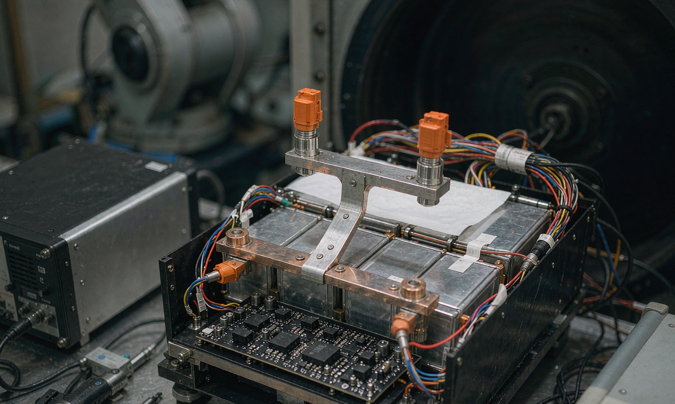
Robots vibrate. AMRs roll over expansion joints and pallet debris. Drone packs experience 5–7 g transient shocks on every hard landing. A battery solution that passes every electrical test on a foam-padded bench can still fail in the field because a copper busbar cracked, a cell swelled against a tolerance gap, or a connector worked loose.
The mechanical sweep I run on every robotic pack has three steps. First, a sweep-vibration test from 5 Hz to 500 Hz at 3 g RMS on each of three axes for two hours per axis, with the cells at 50 percent state of charge, watching for resonance peaks above 7 g with accelerometers mounted on the cell stack and on the enclosure lid. Second, a shock test of 30 g, 11 ms half-sine, three positive and three negative pulses on each axis, again at 50 percent state of charge. Third, a 1 m drop onto concrete, six orientations, twice — because Murphy is more creative than any test lab. After the sweep, I do a full visual inspection, torque-audit every bolted joint to the original spec (M5 at 4–6 N·m, M6 at 8–10 N·m, M8 at 12–14 N·m), and measure DC internal resistance at 0.5 C, 10 second pulse. If the DCIR baseline drifts by more than fifteen percent after mechanical testing, the busbar or the cell-tab interface is suspect and I am not proceeding to electrical cycling yet.
3. Thermal validation at three temperatures, three duty cycles
A battery solution that works at 25 °C tells you nothing about whether it will work on a robot crossing an unconditioned warehouse in August or in a refrigerated food-packing line in February. Thermal validation is the second test I always run, and it has to cover the temperature window the robot actually operates in, not just the cell datasheet’s comfortable 25 °C.
The protocol I use is straightforward: at each of −10 °C, 25 °C, and 50 °C, fully charge the pack to its upper cutoff voltage with the manufacturer’s specified charge profile, rest one hour, and discharge at the I_cont cycle until the pack hits its lower cutoff voltage. At every temperature I log cell voltage spread, surface temperature at six thermocouples (top, middle, bottom of the stack, plus three on the enclosure skin), and the BMS-reported state of charge versus a Coulomb-counted ground truth. The thresholds I apply:
- Capacity at 25 °C must be 100 percent ± 2 percent of rated. Anything outside that band means the pack is undersized, the cells are out of balance, or the BMS calibration drifted in production.
- Capacity at −10 °C should be at least 80 percent of 25 °C rated for an LFP pack, and 70 percent for an NMC pack. Lithium plating below 0 °C during charging is the silent killer of robotic packs that operate outdoors, so I also confirm that the BMS blocks charging below the agreed cutoff (typically 0 °C for LFP, −10 °C for NMC with a heating element).
- Capacity at 50 °C must be at least 95 percent of 25 °C rated for LFP, and 90 percent for NMC. More importantly, the maximum cell-to-cell temperature spread at 50 °C at end of discharge must stay below 6 °C. A 10 °C spread on a robotic battery solution means one cell is starving for cooling and will age two to three times faster than its neighbors.
- Voltage spread at end of discharge must stay under 50 mV at every temperature. Beyond 50 mV, the pack’s usable capacity is limited by the weakest cell, not by the average. Beyond 80 mV, walk away.
4. Cycle life testing that actually predicts field life
Cycle testing is where most battery solution testing programs either earn their keep or become a waste of six months. A standard 1 C charge / 1 C discharge cycle at 25 °C to 80 percent depth of discharge tells you the cell datasheet is honest. It does not tell you how the pack will behave under a robotic duty cycle of short pulses and partial cycles for eight years.
The cycle protocol I run on every robotic battery solution is the duty cycle captured in step one, repeated at three temperatures: 25 °C (the realistic warehouse average), 35 °C (warm-climate worst case), and 45 °C (a thermal-chamber accelerated aging condition, but interpreted cautiously because calendar aging at high state of charge is the dominant mechanism for LFP at high temperatures, not cycle count). Each cycle is logged with energy throughput, peak voltage, peak current, average cell temperature, and the BMS state-of-charge error versus ground truth. I run for at least 200 cycles before sign-off, which is roughly equivalent to 2–3 months of warehouse service, and I pull reference measurements — full capacity, full DCIR, and full voltage-spread scan — every 50 cycles.
The pass criteria after 200 duty cycles at 25 °C:
- Capacity retention ≥ 96 percent. Anything below 96 percent after only 200 cycles is a red flag for cell grade, BMS over-charge tolerance, or thermal management.
- DCIR drift ≤ +12 percent. More than +15 percent DCIR growth at 200 cycles means the pack is on a path to premature power fade.
- Voltage spread at end of discharge still under 50 mV. If the spread has widened to 60–70 mV, one cell is degrading faster and the pack will reach end-of-life while five of the six cells still have 15 percent capacity left.
- BMS state-of-charge error within ±3 percent versus Coulomb counting at every reference point. A robotic battery solution whose BMS drifts 6 percent will routinely under-deliver or over-discharge in the field.
For projects that ship in volume, I keep at least three packs on an accelerated life tester running the same duty cycle at 35 °C for 800 cycles, with monthly capacity and DCIR check-ins, to project calendar life. This is the only honest way to predict whether a robotic battery solution will reach the customer’s five-year warranty without surprise service calls.
5. Safety and abuse testing — UN38.3 plus the four tests that matter for robots
Every lithium battery solution shipping internationally needs UN38.3 certification, and I never skip that. But UN38.3 is the floor, not the ceiling, and robots add three abuse risks that UN38.3 does not cover well. The four tests I add on top of UN38.3 for every robotic pack are:
- External short circuit at the system level. UN38.3 shorts the cell; I short the pack’s external terminals at the load connector with a 20 mΩ copper bus for 30 minutes and verify the BMS, fuse, or contactor interrupts within 5 seconds and no cell exceeds 90 °C surface temperature.
- Mechanical crush on the enclosure, not the cell. A robot colliding with a fixture can crush the pack laterally. I press a 50 mm radius hydraulic ram into the side of the enclosure at 100 kN and verify no thermal runaway propagates across the cell stack within 30 minutes, and the pack voltage collapses within 1 second via the BMS.
- Forced discharge to 0 V and back. A robotic battery solution can be deeply discharged if the robot is stored unpowered for months. I discharge to 0 V at 0.2 C, rest 24 hours, then attempt a normal recharge. The cells must accept a recharge and recover to 95 percent of original capacity within three cycles. If they do not, the cell grade is suspect.
- Thermal propagation test per UL 1973 / UL 9540A. I trigger thermal runaway in one cell via nail penetration and verify the pack design (cell spacing, thermal barrier, venting path) prevents propagation to neighboring cells for at least 5 minutes, giving the robot time to safely shut down and the operator time to evacuate.
I also run IEC 62133-2, IEC 62660-2 / IEC 62660-3, and UL 1973 / UL 9540A as required by the destination market, with the cycle profile in step one feeding the duty-cycle clauses rather than the standard’s default 1 C profile.
6. EMC, ESD, and EMI — the silent killer of robotic controllers
A battery solution that passes every electrical and mechanical test can still bring down a robot if its switching converter dumps conducted emissions back onto the DC bus. The BMS, the pre-charge circuit, and any DC-DC converters inside the pack must be EMC-characterized under load, not at idle. I run a CISPR 25 Class 2 conducted and radiated emissions sweep with the battery solution under the I_cont cycle, plus a bulk-current injection immunity test from 1 MHz to 400 MHz at 200 mA. ESD air discharge at 8 kV and contact discharge at 4 kV must not latch up the BMS or reboot the robot’s safety controller. A robotic battery solution that resets the safety PLC when an operator touches a doorknob has failed before it left the lab.
7. Production-line acceptance and the field-data feedback loop
Validation testing does not end at the engineering samples. Every production pack should ship with a factory acceptance test that includes at minimum: a full capacity cycle with the I_cont profile, a DCIR baseline at 50 percent state of charge, a 30-second vibration sweep on each axis, and a torque audit on every bolted busbar with the joint marked in yellow paint so any drift is visible after six months in the field. The DCIR baseline number goes onto a sticker on the pack, and the same number is logged against the serial number in our traceability database so the field service team can compare it against the value measured during annual maintenance.
The most valuable battery solution testing I do is not in the lab. It is the monthly review of field data from the previous quarter: capacity retention versus service months, DCIR drift versus environment, and the root cause of every warranty claim. Patterns that never showed up in 200-cycle lab testing — connector silver-plating wear, BMS firmware drift after firmware updates, ambient temperature surprises in unconditioned greenhouses — only emerge when you look at dozens of packs across thousands of cycles. That feedback loop is what turns a one-time validation pass into a continuously improving custom battery solution.
Frequently Asked Questions
How long does a complete battery solution testing protocol take?
For a typical 48 V, 50–100 Ah robotic battery solution, the protocol I run takes 8–10 weeks end to end: one week for the mechanical sweep, two weeks for the three-temperature characterization, four to six weeks for the 200-cycle duty-cycle test (in parallel with EMC and abuse testing), and one week for documentation and certification hand-off. Accelerated life testing for warranty projections continues in parallel and feeds back at the 6-month mark.
Can a customer skip the duty-cycle characterization and just run standard cycle tests?
Technically, yes. Practically, it is how you ship a battery solution that fails in the first 90 days in the field. The duty-cycle characterization is what sets the I_cont, I_peak, and I_regen numbers that every other test uses. Without those, you are testing the cell datasheet, not the robotic battery solution you are about to ship.
What is the single most useful test for a small-batch robotic prototype?
If I had to pick one test for a first-article prototype with limited time, it would be the three-temperature capacity test at −10 °C, 25 °C, and 50 °C with a full voltage-spread scan at end of discharge. It catches undersized packs, balance problems, BMS calibration drift, and thermal management issues in a single run, and it costs roughly one week of lab time.
How do you decide between LFP and NMC for a robotic battery solution?
If the robot operates indoors, runs moderate duty, and values calendar life, I default to LFP. If the robot is weight- or volume-constrained — drones, wearable exoskeletons, surgical-assist carts — and accepts shorter cycle life in exchange for higher energy density, I go NMC. For outdoor or wide-temperature robots that sit at high state of charge, LFP again wins because its high-state-of-charge calendar aging at 45 °C is roughly half that of NMC.
Do you always run thermal propagation testing, even on small packs?
Yes, scaled to the pack. On a pack under 1 kWh I do a single-cell nail penetration and verify no propagation within 5 minutes. On larger packs I follow the full UL 9540A protocol with gas analysis and a propagation-versus-no-propagation assessment. Customers who skip this step are the ones who discover, six months after launch, that a single cell failure can take out a $40,000 robot.





