
Battery Solution Performance for Robotics: Duty-Cycle,
When an autonomous mobile robot, an AGV, or a collaborative arm loses its shift to a low state-of-charge cutoff in the middle of a tote transfer, the root cause is almost never the cells themselves. In my eight years of designing battery solutions for industrial robots, the field data shows the same pattern: the pack was sized for nameplate capacity, not for the actual duty cycle. The robot’s job profile — torque bursts, regen spikes, dwell time at idle, ambient swings — defines what battery solution performance robotics really means on the plant floor. This guide is a working framework for engineers who have to defend a runtime number, a thermal envelope, and a safety case for a fleet that runs 24/7.
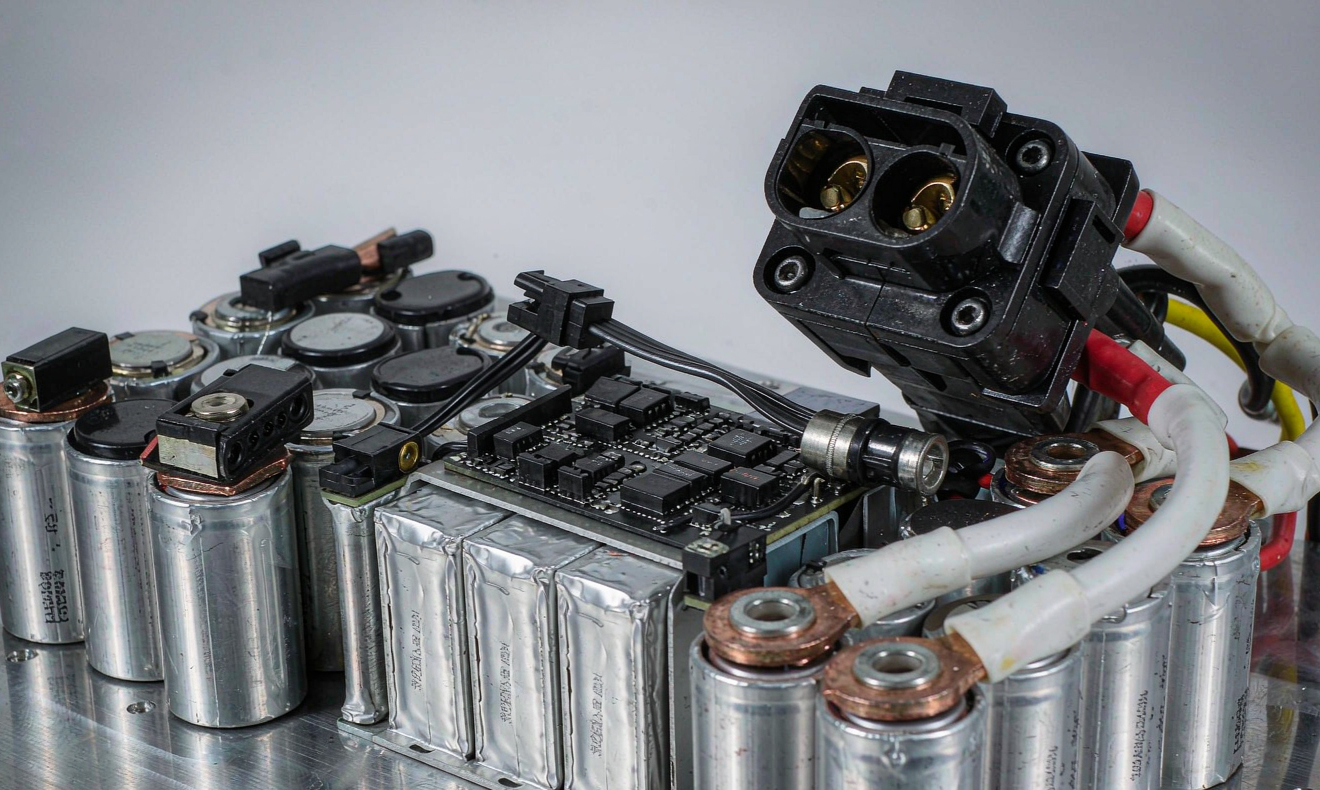
1. Why “performance” for a robot pack is more than a capacity number
The datasheet of a 21700 cell will tell you 4.8 Ah nominal at 0.2 C, 4.3 V max, and 2.5 V cut-off. None of those numbers describe what a tugger pulling 250 kg of payload through a warehouse actually feels. Three factors quietly dominate:
- Duty-cycle weighted current. A warehouse AMR spends roughly 65–80 % of its time on low-current cruise and idle, and 20–35 % on peak acceleration or hoist. The C-rate that defines your pack sizing is the RMS of that waveform, not the marketing peak.
- Thermal derating. Above 40 °C cell skin temperature, usable capacity on most NMC and LFP chemistries drops 5–10 % per 10 °C rise. A pack that delivers 4.2 Ah at 25 °C may only deliver 3.6 Ah at 50 °C without active cooling.
- Voltage sag under pulse load. When an actuator asks for 80 A for 400 ms, internal resistance (DCIR) drags the terminal voltage below the BMS low-cut threshold and the robot faults out, even though the state of charge is still 30 %.
Designing a custom battery solution without modeling those three together is the most common reason robotics fleets replace batteries twice as often as they budget for.
2. Building a duty-cycle profile before you size the pack
I always start a robotics battery project by capturing the load profile over a full shift on at least three representative units. The script is the same every time:
- Sample pack current at 100 Hz with a calibrated shunt or Hall-effect sensor (LEM HASS 100-S is my default).
- Log pack voltage at the BMS terminals, not at the cells, so you include contactor and fuse drop.
- Record skin temperature on at least two cells in the geometric center of the pack and one at the edge.
- Annotate every event: pickup, drop, dock, charge window, idle dwell.
From that log I compute the duty-cycle RMS current (I_rms), the peak duration histogram, and the average state of charge swing per cycle. Those three numbers, plus the worst-case ambient, set every other decision: cell format, series-parallel topology, cooling strategy, and BMS behavior. A robot running I_rms at 0.5 C and peaks at 2 C for <5 s is a different design problem from one at I_rms 0.3 C with 4 C peaks. Both need a lithium battery for robotics, but the cell format and the BMS firmware will diverge dramatically.
3. Cell format and pack topology trade-offs
For mobile robots between 1 kWh and 8 kWh, three formats dominate the line cards we ship:
- 21700 cylindrical (NMC or LFP). Good energy density (180–240 Wh/kg at pack level), excellent thermal conductance, tolerant of high pulse currents. Default for AGVs and service robots up to 5 kWh.
- Prismatic LFP (e.g., 100 Ah or 280 Ah cells). Lower energy density but flatter voltage curve and longer cycle life (often 6,000+ cycles at 80 % DoD). My default for stationary forklift and AMR opportunity-charge fleets.
- Pouch NMC. Highest energy density (260+ Wh/kg) but requires rigid compression frames and careful BMS. I only specify pouch when the payload budget forces it, such as exoskeleton or wearable robotics.
Topology follows the duty cycle. For 48 V-class systems, 13S or 14S LFP is the workhorse; 13S or 14S NMC gives you a tighter voltage window and lighter mass. For 24 V AGV fleets, 7S LFP with a 100 A peak-capable BMS is the common baseline. The mistake I see most often is oversizing voltage to chase a “cleaner” current waveform, then under-sizing the Ah rating to compensate on cost. That trade always costs runtime in the field.
4. Thermal design: passive, conduction, or liquid
If your duty cycle shows I_rms < 0.4 C and ambient < 35 °C, passive cooling with aluminum cell holders and a heat-spreading base plate is usually enough. Above that, you need forced air or a cold plate. A few rules of thumb I apply:
- Keep cell-to-cell delta T below 5 °C across the pack. Anything wider signals uneven cooling and will shorten cycle life on the hot cells.
- Mount temperature sensors on the cell can, not on the bus bar. Bus bar temperature lags by 20–40 seconds and can read fine while a cell is already at thermal limit.
- If you add a fan, drive it from the BMS, not from a separate thermostat. The BMS knows the real SoC and SoH, and can ramp the fan only when needed, saving 1–3 % of pack capacity per shift.
- For fast-charge applications (15–30 minutes opportunity charge), liquid cooling is no longer optional; passive simply cannot shed 2–3 kW of charge heat fast enough.
A well-cooled pack routinely delivers 8–12 % more usable energy over a shift than the same pack run to the same SoC window without active thermal management.
5. BMS firmware behaviors that decide fleet uptime
The BMS is the part of the custom battery solution that the OEM often under-specifies, because the failure modes look like software bugs and not “battery failure.” Five I never ship without:
- Dynamic current limit based on temperature and SoC. Hard-coded 50 A limits are wrong by definition; the limit must fall as the pack warms or as voltage sags.
- State-of-Health tracking with coulomb counting plus capacity recalibration every 30 cycles. Without recalibration, SoH drift will silently shrink fleet runtime by 1–2 % per month.
- Predictive low-cutoff. Cut off at 3.0 V/cell under load, not at 2.5 V/cell. Recoveries are expensive in a warehouse; an extra 5 % of runtime is not worth a service call.
- CAN or RS-485 telemetry to the fleet manager. Every cell voltage, temperature, and SoC, broadcast at 1 Hz minimum. Without that stream you cannot debug anything from a service ticket.
- Field-updatable firmware. Robots are deployed for 7–10 years. The BMS firmware will need to change.
6. Runtime prediction: a back-of-envelope that actually matches the field
Once the pack is sized, I predict runtime with a three-step method that lines up with what I see on real robots within 5–7 %:
- Convert the measured I_rms into an effective C-rate against the pack’s nominal capacity at the average operating temperature.
- Apply Peukert-style correction. For NMC robotics packs I use k ≈ 1.05 at 25 °C rising to 1.12 at 45 °C. For LFP, k ≈ 1.08 across the same range.
- Subtract 8 % for BMS, contactor, and auxiliary loads (fans, lights, controllers). This is the part every spreadsheet forgets.
That third line is where most datasheet-based runtime claims fall apart. A 5 kWh pack does not deliver 5 kWh to the wheels; it delivers about 4.6 kWh to the load after conversion and auxiliaries. When I size for a customer, I always quote the available-at-load figure and put the nameplate figure in the appendix.
7. Safety, certification, and what procurement should actually ask for
Every robotics pack we ship is certified to UN38.3 for transport, IEC 62133 for safety, and UL 1973 or UL 2271 depending on whether the robot is stationary or mobile. For medical, agricultural, or food-grade robots, additional regional standards apply: FDA 21 CFR for medical, ISO 13849 for safety functions, and IEC 60529 for IP rating. For drones and aerial robots that fall into the same product line, EASA SC-LIGHT and FAA Part 107 operator rules add airworthiness context that the ground crew sometimes has to absorb as well.
Procurement teams should request three documents with every quote: the cell UN38.3 summary, the BMS functional safety description, and the pack-level IEC 62133 or UL 1973 certificate. If a vendor cannot produce all three, the pack is not procurement-ready.
8. When to recommend sodium-ion or semi-solid for a robot fleet
Not every robotics application is best served by conventional lithium. Two adjacent chemistries are worth a serious look in 2026:
- Sodium-ion. Lower energy density (120–160 Wh/kg) but excellent low-temperature performance down to −20 °C and much safer thermal runaway behavior. Worth specifying for cold-chain warehouse robots and outdoor agricultural platforms where LFP heaters eat too much of the budget.
- Semi-solid state. Higher energy density (280–320 Wh/kg) and dramatically reduced thermal runaway risk, but at a price premium and with stricter pressure-management requirements during charge. Best fit for high-payload humanoid or humanoid-adjacent platforms where mass is the constraint.
For most AMRs and AGVs in 2026, the right answer is still a well-designed LFP pack with a smart BMS and proper thermal design. The new chemistries earn their place where the operating envelope makes LFP marginal, not as a default upgrade.
Frequently Asked Questions
What is the single biggest cause of unexpected short runtime in a robotics battery?
Duty-cycle undersizing. The pack was sized for nameplate capacity rather than the actual I_rms of the robot, so thermal derating and voltage sag under load eat the headroom the integrator expected.
How often should a robotics battery pack be capacity-tested in the field?
A full reference-charge-discharge capacity test every 90 days is a healthy baseline. Anything longer and SoH drift in the BMS starts to mask real degradation. Anything shorter and the test itself accelerates wear.
Can a BMS firmware update be done without taking the robot offline?
Yes, if the BMS has a dual-bank firmware slot and the pack is in a stable state (idle, not charging, SoC between 30–70 %). The robot can keep running on the old image while the new one writes, then swap on the next opportunity-charge cycle.
Is LFP or NMC the better choice for an opportunity-charged AMR?
LFP is almost always the better choice for opportunity-charged fleets because of its cycle life at high SoC and its flatter voltage curve, which simplifies SoC estimation. NMC wins only when energy density per kilogram is the binding constraint.
How do I size a pack for cold-storage robots that operate at −15 °C?
Use a chemistry with strong low-temperature performance, such as a low-temp LFP variant or sodium-ion, and include self-heating that draws less than 3 % of pack capacity per shift. Pre-condition the pack to 10 °C before each opportunity-charge cycle to keep charge acceptance high.
What telemetry should a fleet manager record to debug runtime complaints?
At minimum: pack voltage and current at 1 Hz, per-cell voltages at 0.5 Hz, two cell temperatures, SoC, SoH, and a duty-cycle event log with timestamps. Without this stream, runtime complaints cannot be distinguished from load-profile drift, BMS drift, or real cell degradation.
How long should a well-engineered robotics pack last in a 24/7 fleet?
Expect 6 to 8 years or 4,000 to 6,000 full equivalent cycles, whichever comes first, when the pack is properly thermal-managed and SoC-windowed between 20 % and 85 %. Packs that spend time at 100 % SoC in hot docks age noticeably faster.





