Lithium Battery Design for Mobility Devices: Cell Choice,
I have spent more than a decade designing lithium battery packs for powered wheelchairs, mobility scooters, and last-mile delivery carts, and if there is one lesson that field returns have taught me, it is this: a mobility battery is not a smaller version of an EV pack. It lives on a frame that vibrates, it gets charged from whatever outlet the user can reach, and it is carried up stairs by people who have never read a datasheet. Good lithium battery design for mobility devices starts with those realities, not with the cell spec sheet.
Why Mobility Devices Punish Generic Battery Packs
A mobility device battery leads a harder life than most consumer lithium packs. It operates outdoors across a temperature range that can swing from -10 °C on a winter morning to 55 °C inside a parked van. It endures continuous vibration from pavement joints, curb drops, and unpaved paths. And unlike a drone battery that a hobbyist recharges after each flight, a mobility pack is often opportunity-charged: plugged in for twenty minutes at a shop, partially discharged again, and expected to deliver consistent torque the whole day.
When I audit failed packs returned from the field, the failure distribution is remarkably consistent. Roughly 60% trace back to connector and wiring fatigue, 20% to BMS protection thresholds that were copied from an e-bike design without validation, and the remainder to cell selection that ignored realistic discharge profiles. Very few failures are actual cell defects. That is why the design phase deserves far more attention than it usually receives.
Cell Chemistry Selection: LiFePO4 vs NMC for Mobility Applications
The first architectural decision is chemistry, and for mobility devices the choice usually comes down to lithium iron phosphate (LiFePO4) and nickel manganese cobalt (NMC) oxide cells.
- LiFePO4 (LFP): 3.2 V nominal, exceptional thermal stability with an onset temperature around 270 °C, and 2,000 to 5,000 cycles at 80% depth of discharge. The trade-off is roughly 15–20% lower gravimetric energy density and weaker low-temperature performance below 0 °C.
- NMC: 3.6–3.7 V nominal, 200–250 Wh/kg at cell level, better cold-weather output, but a tighter thermal runway margin and typically 800–1,500 cycles in this duty cycle.
For wheelchair and scooter platforms where the battery is a permanent asset rather than a consumable, I specify LiFePO4 in most programs. Service life dominates the total cost of ownership calculation: an LFP pack that survives five years of daily cycling beats an NMC pack that needs replacement at year two or three, even if the LFP pack costs 15% more upfront. NMC remains the right answer when the industrial design imposes a hard volume or weight limit — for example folding travel scooters where the pack must stay under airline carry-on thresholds and every watt-hour matters.
Pack Architecture: Voltage, Capacity, and Series Configuration
Most mobility platforms settle on 24 V or 36 V nominal systems. A 24 V pack built from eight LiFePO4 cells in series (8S, 25.6 V nominal) covers the classic power-chair range, while 36 V (12S LFP or 10S NMC) suits heavier scooters and hilly terrain. Practical capacity lands between 10 Ah and 40 Ah, which translates to 256 Wh to 1,024 Wh — a range deliberately chosen because it aligns with airline and transport regulations.
That Wh number is not arbitrary. Under IATA dangerous goods rules and the UN38.3 test summary that accompanies every compliant pack, lithium-ion batteries up to 100 Wh can travel in carry-on baggage without airline approval, and batteries between 100 Wh and 160 Wh require airline approval with a limit of two spares. A 25.6 V / 20 Ah LFP pack comes in at 512 Wh, so it ships as freight (Section IA/IB of IATA PI965) rather than in the cabin. When a customer asks about flying with a mobility scooter, I point them to the FAA guidance: installed mobility batteries can be accommodated, but the airline must be notified and the terminal must be able to disconnect the battery. Designing a quick-disconnect harness is therefore not a convenience feature — it is a travel-enabling feature.
Mechanical and Enclosure Design for Vibration and Impact
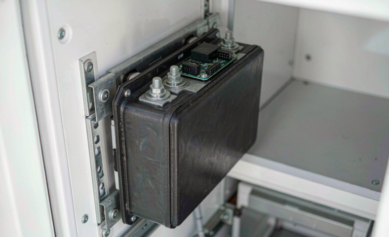
Vibration is the silent killer of mobility packs. A scooter frame transmits broadband vibration from 5 Hz to well over 100 Hz directly into the battery enclosure, and every unresolved resonance multiplies solder-joint fatigue. My standard practices:
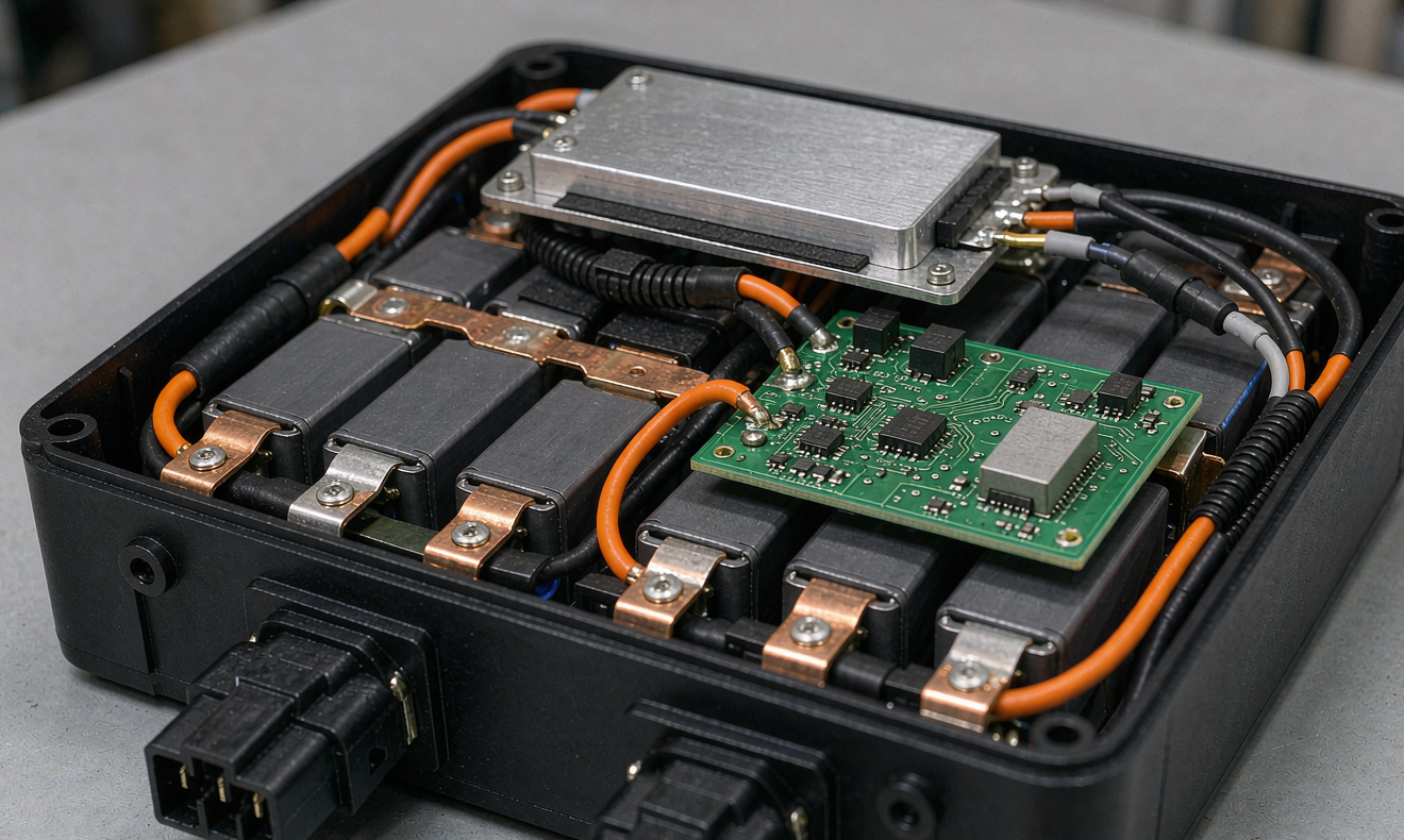
- Cell fixing: prismatic cells are bonded into a laser-cut FR4 or ABS cage with polyurethane adhesive so that no cell face can fret against the enclosure. Loose-wrapped cells with zip ties fail within eighteen months in the field.
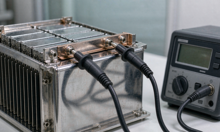
- Busbars over nickel strip: spot-welded nickel strip is acceptable below 15 A continuous, but a 36 V scooter controller can draw 25–35 A peak on a hill start. I use laser-welded copper busbars with nickel plating, sized for at least 2× the peak controller current.
- Strain relief: every wire exiting the enclosure gets a strain-relief gland and a service loop. The 60% connector-failure statistic I mentioned earlier is almost entirely preventable with proper cable management.
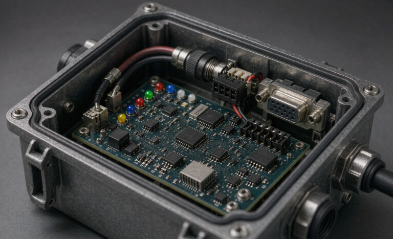
- Ingress protection: IP54 minimum for under-seat mounting; IP65 gasketed enclosures for exposed deck-mounted packs on shared-fleet scooters that get washed with pressure hoses.
For validation we shake samples on a profile that mirrors ISO 7176-25 (the wheelchair standard that references battery mounting robustness) and IEC 60068-2-6 sinusoidal vibration, then finish with a 1 m drop onto concrete on each face. A pack that cannot pass those three tests will not survive two years on a city sidewalk.
BMS Design: Protection Thresholds That Match the Duty Cycle
The battery management system is where generic packs most often disappoint. An e-bike BMS tuned for high discharge bursts will low-balance an LFP mobility pack; a solar-storage BMS tuned for slow charge will nuisance-trip on a hill start. The mobility duty cycle sits in between, so the BMS needs to be specified from real ride data.
On a typical 36 V scooter I collect current traces during a full day of routes — including the steepest local ramp — and size the continuous MOSFET path at 1.5× the worst observed 30-second current, with the overcurrent trip set above the controller’s own limit so the controller, not the BMS, is the primary limiter. Cut-off thresholds matter just as much: LFP cells should not be routinely pulled below 2.5 V, and the low-voltage cut must coordinate with the controller’s own low-battery behavior so the user gets a graceful slowdown rather than a sudden shutoff mid-crossing.
Cell balancing is the other under-specified area. For packs cycled daily for years, a passive balancer bleeding at 60–100 mA is adequate only if the cells are matched within 10–15 mV at shipment. I request cell grading data from the supplier and band-match cells at pack assembly; that single step typically adds 8–12% to pack life and costs almost nothing at production volume.
Finally, for anything sold into medical-adjacent channels, the BMS and pack should be designed and documented against IEC 62133-2, which has become the de facto safety benchmark that notified bodies and procurement officers ask for. Having watched manufacturers scramble during audits, my advice is simple: build the compliance file in parallel with the design, not after it.
Thermal Management on a Modest Budget
Mobility packs rarely justify active cooling, so passive thermal design has to carry the load. Three numbers guide my layout. First, charge acceptance: most LFP cells should not be charged below 0 °C, so packs destined for cold climates deserve a heating pad or at minimum a thermistor interlock that blocks charging until the cells pass 3–5 °C — this one feature eliminates the most common winter warranty claim. Second, discharge heating: a 30 A climb at 3 Ω effective internal path can raise cell core temperature 10–15 °C in twenty minutes, which the enclosure must be able to shed; I allocate at least 15 cm² of aluminum surface per watt of sustained heat. Third, enclosure color: a dark under-seat pack in direct summer sun can see 60 °C ambient, so light-colored or reflective enclosures genuinely extend calendar life.
Custom Battery Solutions: When an Off-the-Shelf Pack Is the Wrong Answer
Some procurement teams default to a catalog 24 V 20 Ah pack because the unit price looks attractive. In my experience that decision costs more within two years. An off-the-shelf pack almost never matches the device’s mounting envelope, its connector standard, its controller current limit, or its fuel-gauge communication protocol — so integrators add adapter plates, pigtail harnesses, and external current limiters, each of which is a new failure point and each of which voids portions of the certification file.
A proper custom battery solution starts from the device: we model the current profile, select cells for the real duty cycle, design the BMS thresholds around the controller, and validate against the standards the market requires (UN38.3 for transport, IEC 62133-2 for safety, ISO 7176-25 context for wheelchairs, EN 12184 for scooters in Europe). The engineering cost is recovered quickly through fewer field returns and a single coherent certification story — which is exactly what distributors and procurement officers ask to see before signing.
A Realistic Development and Validation Checklist
For teams beginning a new mobility battery program, here is the sequence I follow, condensed from a dozen production programs:
- Define the electrical envelope: nominal voltage, continuous and peak current, Wh ceiling for transport rules.
- Log ride data for at least one week across representative users and terrain.
- Select chemistry and cell format against energy, cycle life, and temperature requirements.
- Design the mechanical package for vibration, drop, and ingress per IEC 60068 and IP ratings.
- Specify BMS thresholds from the logged data; match cells at assembly.
- Run UN38.3 transport tests and IEC 62133-2 safety tests at an accredited lab.
- Complete a 200-cycle in-house endurance run before approving the design for mass production.
Frequently Asked Questions
How long does a lithium battery last in a mobility scooter?
A well-designed LiFePO4 pack typically delivers 3–5 years or 1,500+ full cycles in daily mobility use before capacity falls below 80%. NMC packs usually reach that point in 1.5–3 years. Range loss below 70% of nominal is the practical retirement signal for most users.
Can I take a mobility scooter battery on an airplane?
Yes, with conditions. FAA and IATA rules require the airline to be notified in advance, the battery must be a non-spillable or lithium type that passes UN38.3, and terminals must be protected against short circuit. Lithium-ion mobility batteries larger than 160 Wh may require airline-specific approval or may be carried as cargo — check with the carrier before booking, and choose a pack with a quick-disconnect harness to speed the gate process.
Is LiFePO4 safer than lithium-ion for wheelchairs?
LiFePO4 has a significantly higher thermal runaway onset temperature (around 270 °C versus roughly 210 °C for many NMC formulations) and does not release oxygen as aggressively during failure, so it is the chemistry I recommend for devices used by vulnerable riders. Both chemistries are safe when designed, protected, and certified correctly.
What does UN38.3 certification mean for a mobility battery?
UN38.3 is the UN Manual of Tests and Criteria covering altitude simulation, thermal cycling, vibration, shock, short circuit, impact, and overcharge. It is mandatory for transporting lithium batteries by air, sea, or road, and any reputable supplier should provide the test summary on request.
How should I store a mobility device battery during winter?
Charge to roughly 50–60% state of charge, disconnect the pack from the device, and store it between 10 °C and 25 °C. Check the voltage every two to three months and top up if any cell group falls below the storage threshold. Never store a pack fully charged on a cold concrete floor — the combination of high SOC and low temperature accelerates calendar aging.