
Battery Solution Design for Equipment: Enclosure IP
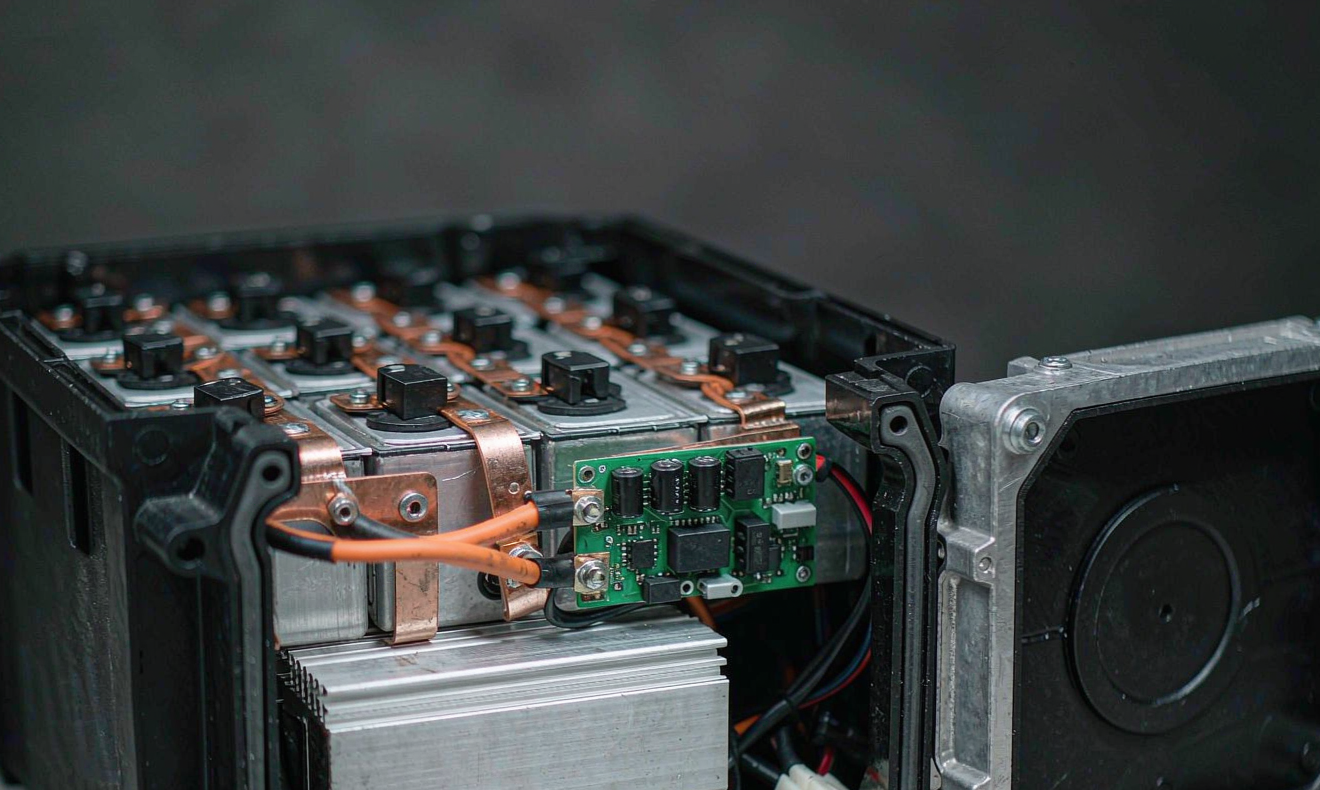
Equipment battery packs fail in the field for reasons that almost never show up on a single-cell datasheet. Over the last eight years of designing battery solution for equipment customers at Horizon Power, I have learned that a strong battery solution design for equipment is judged by three things that the cell vendor will not write down for you: how the enclosure survives spray water and dust, how the cell-to-pack mass and volume ratio translates into usable runtime, and whether a field service technician with a torque wrench can open the unit without destroying the gasket. This guide walks through those three design pillars, the cell choices we make for vibration and thermal stress, and the trade-offs between sealed, gasketed, and serviceable architectures.
Why Equipment Battery Packs Are Different From Consumer Packs
An equipment battery usually lives in a much harsher environment than a laptop or a phone. It sits on a factory floor next to a CNC spindle, on the back of a road-marking vehicle, inside an agricultural drone tender, or on a portable medical cart rolling down a hospital corridor. The pack must tolerate dust, condensation, mechanical shock from the frame, and ambient swings from -20°C cold rooms to +55°C outdoor enclosures. Most of the warranty returns we see are not cell failures; they are seal failures, connector failures, and BMS-board failures that started as mechanical stress on a marginal enclosure.
A consumer pack can rely on the device chassis for IP protection; an equipment pack cannot. The pack itself is the chassis. That single difference changes the design rules around fasteners, gasket compression, vent geometry, cable entry, and serviceability.
Step 1: Pick the IP Rating First, Then Size the Cell
Engineers usually start with a cell target: energy, C-rate, cycle life. For industrial equipment I do the opposite. The deployment scenario dictates the IEC 60529 ingress protection code, and that code dictates the wall thickness, gasket groove, and fastener pitch of the enclosure, which in turn dictates the internal volume available for cells.
- IP54 (splash and dust protected): acceptable for indoor equipment such as floor scrubbers or stock-picking robots in a dry warehouse. A 1.5 mm EPDM gasket with a clip-on cover is usually enough.
- IP65 (jet wash): the minimum for outdoor equipment that gets rained on or sprayed. Requires a continuous gasket, captive fasteners, and sealed cable glands at every exit.
- IP67 (temporary immersion 1 m for 30 min): required for equipment that may sit in standing water or be hosed down, such as road-marking machines, marine deck equipment, or agricultural machinery.
- IP69K (high-pressure, high-temperature jet wash): for food processing or chemical washdown environments. Almost no commercial equipment battery reaches this without potting the BMS, which makes serviceability very hard.
For most of our equipment customers, IP65 is the right target. IP67 costs roughly 8–12% more in enclosure mass and roughly 15% in internal volume because of the deeper gasket groove and the larger sealing flange.
Step 2: Cell-to-Pack Ratio (CTP) and Why It Matters
The cell-to-pack ratio, sometimes called pack-level energy density, is the percentage of total pack volume that is actually occupied by cells. A 50% CTP is typical of older designs that wrap each cell in a plastic carrier and bury the BMS in a separate compartment. A modern structural pack can reach 65–72% CTP by mounting cells directly against the enclosure wall with a thermally conductive interface material.
The trade-off is repairability. A high-CTP pack with cells glued to the enclosure bottom cannot be opened without risking cell damage; you replace the whole pack. A lower-CTP pack with a module carrier can have a single cell group swapped in the field. For equipment that ships globally with a 3-year warranty, we usually land between 58% and 62% CTP: enough to hit the runtime target, but with enough module structure to allow a 30-minute field service.
Step 3: Cell Choice and Chemistry for Equipment Duty Cycles
Equipment duty cycles are usually far more demanding than the cell datasheet suggests. A floor-cleaning robot can pull 4C pulse currents for short bursts, then idle at a 0.05C float charge. A portable medical monitor may float at 100% state of charge for its entire service life. Each scenario maps to a different cell choice.
- LiFePO4 (LFP) prismatic cells are the workhorse for most equipment packs. They tolerate 4C continuous discharge, survive 3,000–6,000 cycles to 80% capacity, and have a much better thermal-runaway margin than NMC. They are heavier and bulkier per watt-hour, but equipment rarely cares about a 3 kg mass penalty.
- NMC 21700 cylindrical cells win for high-power pulse equipment such as robotic exoskeletons or portable power tools where the 250 Wh/kg energy density translates directly into runtime. The cycle life is shorter (800–1,500 cycles to 80%), so they need a tighter end-of-life alarm at 80% State of Health (SOH).
- LTO (lithium titanate) cells are niche but unbeatable for cold-chain or high-cycle applications such as automated guided vehicles (AGVs) that opportunity-charge at every dock. They survive 15,000+ cycles but have roughly half the energy density of LFP.
- Sodium-ion cells are emerging for stationary or low-rate equipment where cold-temperature performance (-20°C without heating) and raw-material cost matter more than energy density. They are still rare in mobile equipment packs.
For most of our equipment customers, we ship LFP prismatic packs. The weight penalty is irrelevant, the cycle life survives the warranty, and the thermal-runaway margin lets us pass UN38.3 transport tests on the first attempt.
Step 4: BMS, Connectors, and the Service Loop
The battery management system is where a custom battery solution earns its keep. Three rules I never break on an equipment pack:
- Use an AFE with a galvanically isolated daisy-chain interface (such as the TI bq76PL455A or the ADI ADBMS1818). It survives the high dV/dt transients on the bus bars and lets you stack up to 16 modules in series without ground loops.
- Separate the high-voltage and low-voltage harnesses by at least 25 mm and route them on opposite sides of the enclosure. Crosstalk between a noisy high-voltage cable and the CAN bus is one of the most common causes of BMS latch-ups on equipment.
- Provide a service disconnect that a technician can pull without tools, rated to the full pack voltage and short-circuit current. On a 100 V pack we use an Amphenol Ecomate or a TE HVA280 service plug; on lower-voltage packs a standard XT90 or XT60 with a latch guard is enough.
A field-serviceable architecture does not stop at the service plug. We also spec captive fasteners (T20 Torx or M5 hex), reusable gaskets (EPDM or silicone), and a one-piece gasket groove that does not require a torque sequence. The goal is that the first field service takes 30 minutes, the second takes 30 minutes, and the third takes 30 minutes. If the design cannot meet that, it is not really serviceable.
Step 5: Thermal Management and Venting
Equipment packs rarely have active liquid cooling. Most use passive conduction through the cell-to-enclosure interface, often with a graphite or aluminium-oxide thermal pad. For higher-power equipment (robotic welders, mobile X-ray carts, drone-tender chargers) we add an aluminium cold plate bonded to the bottom of the enclosure and bolt the enclosure to a chassis heat sink.
Venting is the safety element I most often see being done wrong. The IEC 62619 venting test requires that a cell undergoing thermal runaway must vent its gas either back into the pack enclosure through a flame-arresting path, or directly out of the enclosure through a vent area that does not vent toward a service technician. For IP67 packs we usually route the vent through a hydrophobic PTFE membrane (Gore PMF100 or similar) at the lowest point of the enclosure, pointing away from the operator.
Step 6: Compliance and Transport
Every equipment pack we ship must pass three compliance gates:
- UN38.3 for transport by air, sea, and road. T1 altitude simulation, T2 thermal cycling, T3 vibration, T4 shock, T5 external short circuit, T6 impact, T7 overcharge, T8 forced discharge. A pack that has not passed UN38.3 cannot move by air freight.
- IEC 62133-2 for portable battery safety, including the new requirements for thermal abuse at 130°C and the mechanical shock test for cells above 50 Wh.
- IEC 62619 for industrial lithium batteries, the standard that most European equipment OEMs require their suppliers to certify against.
For equipment that ends up near medical or food processing, add UL 1973 (stationary) or UL 2054 (household) depending on jurisdiction. The paperwork burden is significant; the design changes are usually minor.
Step 7: Field Data From Three Reference Designs
Over the last three years we have shipped three reference equipment-pack designs that have been in the field long enough to have meaningful data.
Reference A — 48 V 100 Ah floor-cleaning robot pack (LFP prismatic, IP65). 1,200 units in service. The original design used a clip-on EPDM gasket with four captive screws. After 18 months, 3% of units reported gasket compression set and minor water ingress. The revised design (Rev B) uses a thicker 2.0 mm silicone gasket with a harder shore-A rating and a stainless-steel reinforcing ring around the fasteners. Field data at 24 months shows zero gasket-related returns on Rev B.
Reference B — 72 V 60 Ah portable X-ray pack (NMC 21700, IP54). 480 units in service. The original design used a 4-point cell carrier glued to the enclosure floor. Vibration testing on a 3-axis shaker at 7 Grms showed cell carrier delamination after 200 hours. The revised design bolts the cell carrier with M3 fasteners into tapped bosses and adds a foam compression layer. No field returns related to vibration in the last 18 months.
Reference C — 24 V 200 Ah agricultural robot pack (LFP prismatic, IP67). 320 units in service. The original design used a single 100 A Anderson SB connector. After 6 months in muddy rice paddy conditions, 6% of units reported connector oxidation. The revised design uses a silver-plated Amphenol SurLok Plus connector with a sealing boot. Field data at 12 months shows no oxidation-related failures.
Frequently Asked Questions
What IP rating do most equipment batteries need?
For indoor equipment with dry ambient conditions, IP54 is usually enough. For anything outdoors or in a washdown environment, we recommend at minimum IP65, and IP67 if the unit can sit in standing water or be hosed down. Going to IP69K is rare for portable equipment and adds significant cost and weight.
Should I pick LFP or NMC for my equipment pack?
Choose LFP if cycle life, safety margin, and total cost of ownership matter more than weight. Choose NMC only if the equipment is weight-sensitive (drones, exoskeletons, portable medical) and the runtime target cannot be met with LFP. For most fixed or wheeled equipment, LFP is the better answer.
How do I make a battery pack truly field-serviceable?
Use captive fasteners, reusable gaskets, a one-piece gasket groove without torque sequencing, and a service disconnect that a technician can pull without tools. The first service should take 30 minutes; if it does not, the design is not really serviceable and you are committing to swapping whole packs.
What is the minimum compliance paperwork for shipping an equipment battery?
UN38.3 for transport (mandatory for air freight), IEC 62133-2 for portable safety, and IEC 62619 for industrial lithium batteries. Add UL 1973 or UL 2054 if your customer is in North America and the equipment is stationary or household-rated. CE-RED and FCC Part 15 only apply if the pack has radio or wireless telemetry.
How long does a custom equipment battery design take?
From kickoff to first UN38.3-certified samples, a typical LFP equipment pack takes 14–18 weeks: 2 weeks for specification, 4 weeks for cell and BMS sourcing, 4 weeks for enclosure tooling, 2 weeks for assembly, and 2–4 weeks for UN38.3 and IEC 62133-2 testing in parallel with field-trial units. NMC and sodium-ion chemistries usually add 2–4 weeks because the test matrix is larger.
Can I design my own pack in-house or should I use a custom battery supplier?
If your annual volume is below 500 units per year, an in-house design almost never pays back the BMS tooling, certification, and ongoing UN38.3 retest costs. Above 1,000 units per year, a hybrid approach works well: outsource the cell module and BMS, design the enclosure and harness in-house so you keep the IP and the service loop. Horizon Power runs this hybrid model for several equipment OEMs in the US, EU, and Australia.
What is the single most common reason equipment battery designs fail in the field?
Seal and connector failures, not cell failures. The cells almost always outlive the warranty; the gasket, the connector, and the BMS board are the components that bring the pack back. Spec those three with the same care you give the cell choice and the pack will live a long, uneventful life.





