Lithium Battery Testing for Power Tools: Pulse Load
Over the past decade I have personally signed off on lithium battery testing programs for more than forty cordless power tool platforms — drills, impact drivers, angle grinders, rotary hammers, and chainsaw-class tools. If there is one lesson that field returns have taught me, it is this: a power tool battery that has never been properly tested will find its own way to fail, usually in the hands of your angriest customer. A battery pack for a cordless drill is not a gentle load. It lives in a world of 25C pulse discharges, dusty job sites, drops from scaffolding, and chargers that sit in the sun on a truck dashboard all afternoon.
This article is the testing playbook I wish someone had handed me in 2015. It covers how professional lithium battery testing for power tools differs from testing for consumer electronics, which test sequences actually predict field failures, how to structure a pulse load cycling program, when a thermal abuse chamber earns its cost, and how IEC 62133-2, UL 2595, UN 38.3 and IEC 62841 verification fit together into a compliance path you can defend in an audit.
Why Power Tool Batteries Are a Different Testing Problem
A smartphone battery peaks around 1C discharge. A cordless drill can demand 30 amps from a 2.5 Ah pack — that is over 12C — and impact drivers spike far higher for tens of milliseconds. Power tool packs are among the most electrically and mechanically abused lithium batteries sold to consumers, which is why lithium battery test programs designed for phones fail miserably when applied to tools.
Three characteristics define the testing problem:
- Extreme pulse loads. Lockup events on an impact wrench can transiently exceed 40C discharge. Anything hot-spot related — weld quality, busbar resistance, cell internal resistance mismatch — will surface here first.
- Thermal and mechanical chaos. Packs get left in hot trucks (55 °C+), dropped onto concrete, and stored at 0% SOC over winter. Your test matrix must cover all three abuse vectors.
- Fast-charge expectations. Professional users now expect a 4 Ah pack charged in under 30 minutes. That is roughly 8C charge, which stresses lithium plating margins in a way consumer products never see.
When we review a failed customer-return pack, the dominant root causes are, in my experience of teardown records: spot-weld delamination on the positive terminal (roughly a third of pulse-related failures), BMS FET overheating under repeated stall events, cell-to-cell imbalance from unsorted capacity bins, and water ingress through the gauge pocket or vent holes. Notice that all four are invisible in a simple capacity check — they only reveal themselves under pulse, thermal, or environmental stress testing.
Baseline Electrical Characterization: What to Measure Before Anything Else
Every testing program starts with characterization, because you cannot detect drift without knowing the initial state. For each cell lot and each pilot pack build, we record:
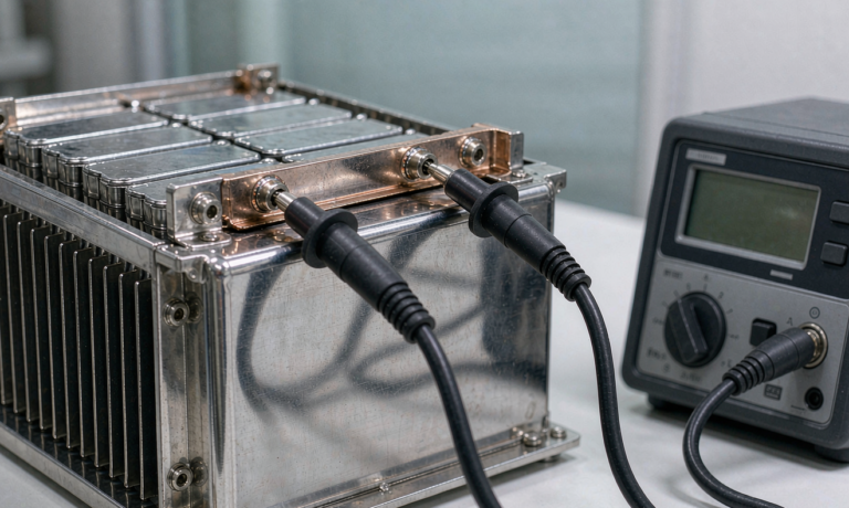
- Open-circuit voltage (OCV) and AC internal resistance (1 kHz) for every cell, with full data retention. A 100% check is non-negotiable for cells entering a high-drain pack; DC IR at 10C pulse (5–30 s windows) is more predictive for power tools than AC IR alone.
- Capacity at 0.2C and at 10C. The gap between these two numbers is your high-drain efficiency. A premium 21700 cell might deliver 95% of rated capacity at 10C; a mediocre one drops to 82% and runs 15 °C hotter. That difference decides whether your grinder has real cutting torque.
- DC pulse resistance mapping at 10%, 50%, and 90% SOC in both 1-second and 10-second pulse windows. This maps directly to the job-site experience: how the tool feels when driving a long structural screw.
- Self-discharge screening: 7-day storage at 40 °C, then OCV re-check. Cells dropping more than 2–3 mV relative to lot median get quarantined — this is the cheapest early filter for micro-shorts that would otherwise become a warranty claim in month nine.
I insist that cell lot data stays linked to pack serial numbers. When a field failure comes back two years later, the first thing I ask for is the cell lot and the incoming inspection record. Without that traceability, root cause analysis is guesswork.
Pulse Load Cycling: Simulating the Job Site in the Lab
Constant-current cycling is nearly useless for power tools; real users never draw constant current. The industry standard approach — and what we run in our own lab — is a duty-cycle profile that mimics actual tool work. A representative impact driver cycle looks like this: 3 s at 15C discharge, 2 s at 5C, repeat for 25 s, then 8 s rest. An angle grinder profile is more continuous: 30 s at 8–10C, 5 s rest. A hammer drill under load mixes 5 s bursts at 20C with 3 s recovery periods.
A proper pulse load cycling program should include:
- 1,000 to 2,000 duty-cycle repetitions with capacity check every 200 cycles. For pro-grade packs we want ≥80% capacity retention and ≤35% DCIR growth at end of test.
- Stall/lockup simulation: every 100 cycles, apply a hard short-duration peak (35–40C equivalent or to BMS current limit) for 0.5–1 s. This is where weld quality and busbar design fail — I have watched a marginal nickel-steel weld joint glow and separate on repetition 400 of exactly such a test.
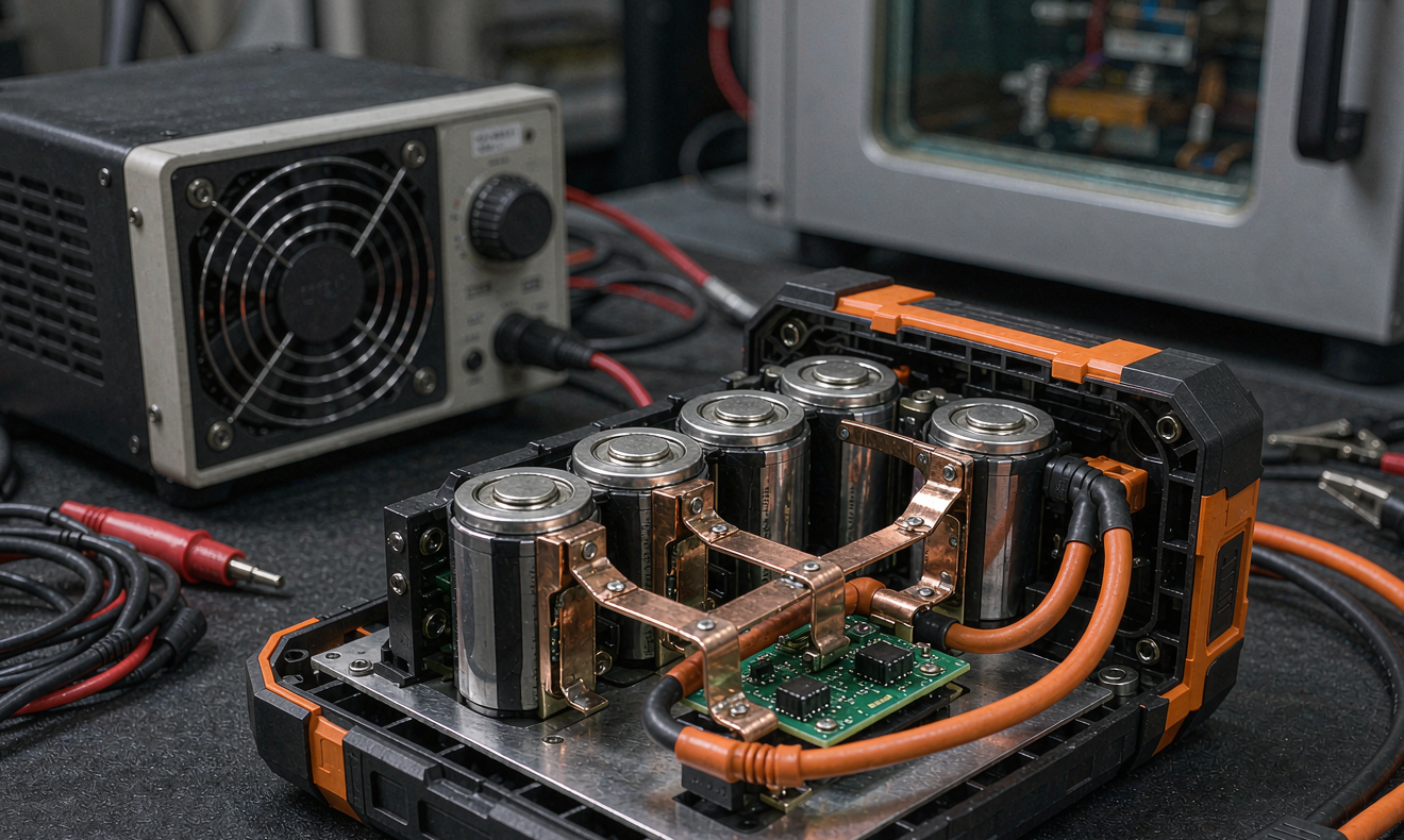
- Temperature instrumentation: thermocouples on cell surface, busbars, BMS FETs, and pack shell. Any point exceeding 80 °C surface temperature under the duty cycle is a design red flag, even if cycling continues.
- Cold pulse testing at −10 °C: high-drain pulses from a cold pack reveal the true low-temperature current capability and BMS protection behavior. Cheap packs either shut down (angry user) or push cells past safe lithium-plating limits (dangerous pack).
The difference between a pack that passes 500 cycles and one that passes 1,500 is rarely the cell datasheet — it is the interconnect engineering, the BMS thermal layout, and the spot weld parameters that production must hold. Pulse cycling is how you verify those before your customers do.
Thermal Abuse Chamber Testing: Where Margins Get Proven
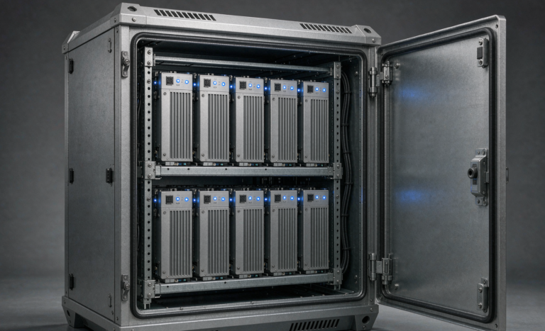
A thermal abuse chamber is the single most expensive piece of test equipment for this product class, and also the one that prevents the failures with actual safety consequences. Our standard sequence for a new pack design includes:
- Hot storage endurance: 7 days at 60 °C and 7 days at 70 °C at 50% SOC. Packs must show no leakage, no venting, and capacity recovery within 5% after return to ambient. Real packs see truck cabs in Arizona summer; this is the closest benign simulation.
- Thermal cycling: −20 °C to +60 °C, 30 cycles, with functional checks (full discharge) at both temperature extremes. Housing materials, gaskets, and potting compounds get exposed for their true behavior here — I have seen ultrasonic weld seams crack open at cycle 14.
- Hot charge testing: charging at 45 °C and 50 °C to verify the BMS charge-inhibit thresholds actually work. Cell makers specify charge cutoff at 45–55 °C; the BMS must enforce it, and the only way to know is to test it deliberately.
- Rapid thermal transition: directly moving a cold pack (−10 °C) into a hot chamber (+55 °C) and checking for condensation-induced leakage current paths on the BMS. This mirrors a winter job site pack thrown into a heated truck overnight.
For safety certification testing — the abuse end — the chamber and associated fixtures must support hotbox testing (130 °C per IEC 62133-2 cell-level requirements, and pack-level exposure per UL 2595), thermal shock, and overtemperature charge to failure under a blast-rated enclosure. You are not trying to make packs fail; you are confirming that when they do, the failure mode is a controlled vent rather than a rupture or flame.
Mechanical and Environmental Testing: Drops, Vibration, Ingress
Power tool packs are the most dropped consumer battery product category. Our mechanical suite reflects that reality:
- Drop testing: 1.0–1.5 m onto concrete, six orientations, from both bare pack and mounted-on-tool configurations. Post-drop requirements: no case cracking, no cell displacement visible on CT scan, full electrical function, insulation resistance >100 MΩ at 500 VDC.
- Vibration testing: random vibration per IEC 60068-2-64 for 2 hours per axis, then resonance search on the cell hold-down structure. A pack that survives drops but fatigues on an oscillating sander’s vibration spectrum is a real failure mode we have reproduced.
- Crush and impact: 13 kN flat-surface crush or the 9.1 kg pendulum impact per UL 2595, verifying no fire, no explosion, and post-test temperature stability.
- Ingress protection: IP54 minimum for standard packs, IP65 for “job-site tough” models — tested with the tool interface open, because dust entry through the rail connector is the classic blind spot. Water intrusion plus a damaged cell wrapper is a corrosion-driven self-discharge factory.
Environmental testing rounds it out: 95% RH humidity storage at 40 °C (300 h) to check insulation resistance, salt-fog exposure for coastal-market SKUs, and altitude simulation at 11.6 kPa equivalent for air-transport compliance context.
The Certification Stack: IEC 62133-2, UL 2595, UN 38.3, and IEC 62841
Compliance for power tool batteries is a stack, and understanding which layer answers which question keeps your certification budget sane. Here is how I explain it to product managers:
- IEC 62133-2 is the baseline cell safety standard for portable sealed lithium cells — the one IEC-mark regulators most commonly reference. It covers short circuit, overcharge, forced discharge, crush, thermal abuse, and design evaluation at the cell level. For lithium battery testing of power tools sold internationally, IEC 62133-2 cell certification from your cell vendor is the foundation; verify scope, construction match, and that the certified cell design is what actually ships to you.
- UL 2595 covers the finished battery pack for portable applications in the North American market. It is pack-level: enclosure, BMS protective functions, abnormal charging, short circuit, drop, and mold-stress tests. North American retailers increasingly treat UL 2595 as a purchase requirement.
- UN 38.3 is not optional for anyone: it is the transport prerequisite for shipping lithium batteries by air, sea, or road. Tests T1–T8 (altitude, thermal, vibration, shock, external short, impact/crush, overcharge, forced discharge) run on the pack and, at 38.3.3 level, on cells. Every design iteration that changes cell count, chemistry, or mass needs a delta review against your existing 38.3 report.
- IEC 62841 series covers the power tool itself (the machine standard), but its battery-related clauses — battery detachment, terminal protection, and the interaction between pack and tool — mean your pack design team should review the tool standard too. I have watched a pack pass UL 2595 while the combined tool-plus-pack configuration created an untested finger-probe path to live terminals.
One practical warning from audits: certificate scope creep is real. When your cell vendor updates an electrode coating or a tab design, their IEC 62133 report gets a new revision — and your pack-level compliance chain inherits a gap until you reconcile it. Build a compliance matrix linking pack SKU → cell type → cell certificate revision → pack certificate, and re-verify it quarterly.
Production-Line Testing: Keeping the Certified Design Honest
Certification proves the design; production testing proves every unit. The minimum line-end suite we implement for power tool packs:
- 100% OCV and IR scan of every finished pack, with SPC control charts. A drift in mean IR of even 2 mΩ across a week of production has flagged weld electrode wear for us twice.
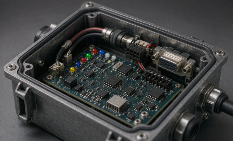
- 100% functional BMS verification: simulated overcurrent trip, overcharge cutoff, over-discharge cutoff, and thermistor plausibility — each pack gets exercised, not sampled.
- Leak/pressure decay or helium check on sealed packs, since visual inspection cannot see a 50-micron seam void.
- Audited EOL capacity check on a sampling basis (1–2% of lots) plus periodic pulse-profile spot checks that replay the lab duty cycle at reduced cycle counts.
- Traceability scan: pack serial ↔ cell lot ↔ BMS firmware version, written into the test database. Every warranty return should be traceable to its production week within minutes.
The most expensive quality failure I have witnessed was not a lab miss — it was a production shift where the spot weld current drifted for two days and roughly 6% of that week’s packs developed intermittent positive-terminal resistance within four months. Line SPC on weld resistance correlation would have caught it on day one.
How We Structure a Full Validation Program
For clients who ask what a complete validation looks like, here is the sequence I recommend, totaling roughly 12–16 weeks for a new pack platform:
- Phase 1 — Design verification (weeks 1–4): characterization, pulse profile development from real tool current captures, thermal imaging under duty cycle, BMS threshold verification.
- Phase 2 — Endurance (weeks 3–10, overlapping): 1,000+ pulse duty cycles, hot/cold storage, thermal cycling, vibration, drops — run in parallel on pilot builds.
- Phase 3 — Compliance (weeks 6–12): UN 38.3, IEC 62133-2 reconciliation, UL 2595 pack testing at an accredited lab.
- Phase 4 — Pre-production audit (weeks 12–16): line-end test verification, SPC baseline, traceability dry run, and a production-intent 200-cycle pulse check on mass-tooled samples.
Skipping Phase 4 is the mistake I see most often. The tooling change from prototype to production — new weld fixtures, new busbar batch, sometimes a different BMS assembler — invalidates part of your earlier data. A focused 200-cycle pulse program on true production parts costs two weeks and has saved at least three of our clients from a first-batch field failure.
FAQ
How long does lithium battery testing for power tools take?
A full new-design validation, including endurance cycling, environmental, and third-party certification testing, typically runs 12–16 weeks. A delta validation on an existing platform — new housing or updated BMS firmware with the same cells — can often be completed in 4–6 weeks by running only the affected test legs.
Is IEC 62133-2 certification enough to sell power tool battery packs?
No. IEC 62133-2 certifies the cell, not your pack. For most markets you additionally need pack-level certification (UL 2595 for North America, IEC 62133-2 pack-level or local equivalents elsewhere), plus UN 38.3 for transport. The tool itself falls under IEC 62841. Treat these as complementary layers rather than alternatives.
What is the most common cause of power tool battery failure in the field?
In our teardown data, the leaders are spot-weld or busbar joint degradation under pulse loads, BMS overcurrent component overheating during stall events, and water/dust ingress through the tool interface. All three are invisible to simple capacity checks and are only caught by pulse load, stall simulation, and ingress testing.
How many pulse cycles should a quality power tool battery survive?
For professional-grade packs, we specify ≥500 full-duty-cycle repetitions to 80% capacity retention as a minimum acceptance gate, with design targets of 1,000–1,500 cycles. Consumer-grade packs typically target 300–500. Remember that one “cycle” in a duty-cycle profile represents far more energy throughput and stress than a gentle 1C lab cycle.
Do I need thermal abuse chamber testing if my cells are already certified?
Yes. Cell certification proves the cell design tolerates abuse, but your pack adds housing, interconnects, potting, and a BMS that change thermal behavior. Hot storage, thermal cycling, and hot-charge verification at pack level routinely uncover gasket failures, seam cracks, and BMS threshold errors that cell certificates cannot predict.
What does UN 38.3 testing include for a power tool pack?
Eight tests: altitude simulation, thermal cycling, vibration, mechanical shock, external short circuit, impact/crush, overcharge, and forced discharge. Packs are tested at specific states of charge, and shipping documentation (including state-of-charge limits of 30% for air transport of standalone lithium-ion batteries) derives from this framework.
Testing a power tool pack properly is not about collecting certificates — it is about reproducing, in a controlled way, the abuse your customers will deliver for free. Every test hour in the chamber is a warranty return you never open.