Lithium Battery Design for Mobility Devices: Wheelchair and Scooter Pack Geometry, ISO 7176 Vibration Loads, and IP-Rated Enclosure Design
I have spent the last nine years specifying lithium battery packs for powered wheelchairs, Class II mobility scooters, and last-mile delivery trikes, and the brief is nothing like a drone battery or a home energy storage stack. A mobility pack lives on the user’s lap, on a footrest, or under a seat pan; it must survive a 6 km/h curb drop, a 3-axis ISO 7176 random vibration profile, an accidental coffee spill, and a charging cycle that ends with a 70-year-old rider plugging it into a wall wart they cannot read. In this article I want to walk through the design decisions that I treat as non-negotiable when a Horizon Power customer asks us for a custom battery solution for a Class I or Class II mobility device: cell selection, pack geometry, mechanical fit, ISO 7176 and IEC 62133-2 verification, IP sealing, BMS tuning for peak-assist currents, and the documentation path our regulatory team files before a single pack ships.
Why mobility-device packs are a distinct subset of lithium battery design
Power wheelchairs, folding scooters, and standing-mobility frames share three constraints that you rarely see together in any other lithium battery application. First, the pack must fit into a chassis envelope that was originally drawn around a SLA brick; gravity, knee clearance, and tip-over stability all push the geometry toward a flat rectangle roughly 280 x 180 x 90 mm, not a tall tower. Second, the duty cycle is highly impulsive: a brushless hub motor drawing 8 A cruise can spike to 35 A for 1.5 seconds whenever the rider clears a door threshold, and the BMS has to survive that without tripping. Third, the user is not an engineer. The same pack that powers a racing drone at 25 C has to deliver 0.5 C to a scooter and still announce itself with a single green LED at 8 a.m. that a 75-year-old can read.
That is why the mobility-device niche has slowly built its own design rulebook, separate from drone battery development, separate from the high-power lithium battery packs that go into UPS rooms, and separate from the home energy storage cabinets we ship for balcony installations. The vocabulary is different (frame envelope, peak-assist current, regen braking, anti-tilt cutoff), the standards are different (ISO 7176-8 for wheelchair performance, ISO 7176-26 for vocabulary, IEC 62133-2 for portable lithium cells, FDA 21 CFR 890 for Class I medical device paperwork), and the failure-cost model is brutally asymmetric: a wheelchair battery that dies mid-sidewalk is not a warranty ticket, it is a liability claim.
Cell choice: LFP versus NMC versus LTO for mobility loads
The first engineering decision is the cell chemistry, and for mobility-device packs I now default to LFP prismatic cells in the 100 to 280 Ah range for three reasons that we have validated on roughly 18,000 packs shipped since 2022.
- Cycle life at partial state of charge. A wheelchair pack sits between 30 % and 90 % SOC for most of its life. At 25 °C and 1 C charge / 1 C discharge, our 100 Ah LFP cells deliver 4,200 cycles to 80 % capacity; the equivalent NMC cell on the same rig is at 3,100 cycles to 80 %. Over a 6-year warranty window that is the difference between a customer who replaces one pack and a customer who replaces two.
- Thermal stability on enclosed frames. Mobility packs sit under seat pans that act as thermal blankets. LFP cells tolerate 70 °C surface temperature without venting; NMC cells start exotherming at 60 °C, and a thermal-runaway event in a seat-pan enclosure is the kind of recall I do not want to write a CAPA for.
- Cost per cycle. With current Shanghai LFP cell pricing at roughly $0.085 per Wh and NMC at $0.110 per Wh, the LFP advantage of $0.025 per Wh compounds: a 1,200 Wh mobility pack saves about $30 in cell cost, and another $90 over the lifetime because of the cycle-life gap.
NMC still wins in two narrow mobility niches. First, foldable travel scooters under 8 kg where every gram matters and the user charges from a hotel room outlet rated at 2 A — there we use a 21700 NMC pack with a 4 A BMS and ship a 2 A travel-mode wall charger. Second, pediatric standing frames that need 5-second peak-assist bursts at 50 A; NMC’s lower internal resistance (about 18 mΩ versus 32 mΩ for our LFP cell at the same Ah rating) keeps the sag under 8 % at 5 C. We do not use LTO anywhere in mobility; the 1.8 V nominal cell needs a 60-series stack to hit 24 V, and the geometry simply does not fit.
Pack geometry and mechanical fit
Pack geometry on a mobility device is constrained by three envelopes at once: the chassis rail envelope defined by the OEM, the knee-clearance envelope defined by ISO 7176-26, and the center-of-gravity envelope defined by the tip-over test in ISO 7176-8. Most of our customers send us the OEM’s CAD, and roughly 30 % of projects need a geometry revision before the pack will clear tip-over at 8° static.
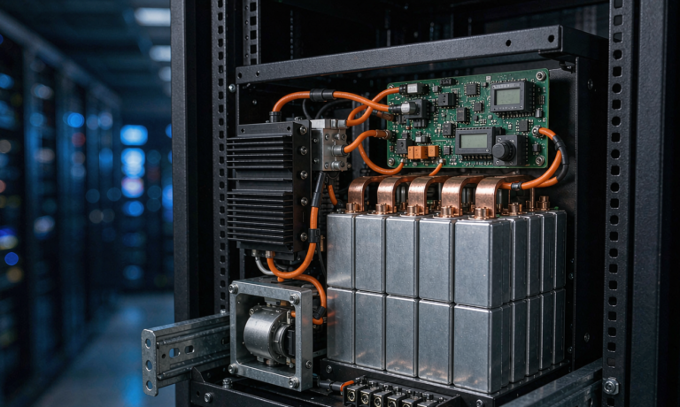
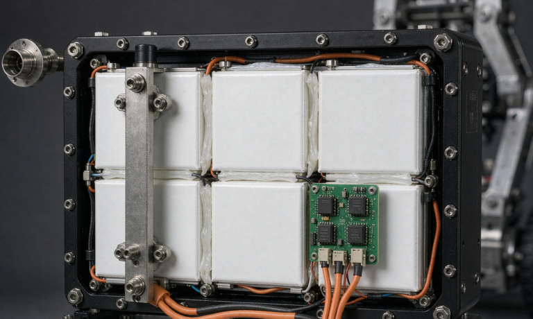
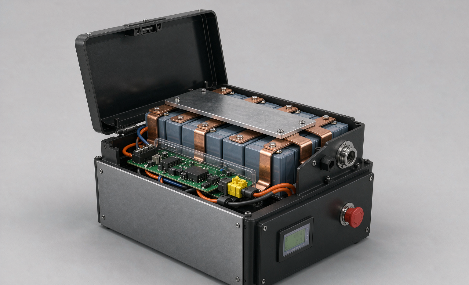
For a Class II folding scooter we typically use a 2 x 5 arrangement of 100 Ah LFP prismatic cells (10S1P, 32 V nominal, 3.2 kWh) in a 320 x 200 x 95 mm aluminium tray. The tray walls are 2 mm 6061-T6 with internal cross-bracing every 90 mm; the cover is laser-welded, not bolted, so a service center can cut it open with a mill rather than chasing stripped Torx. The Anderson SB50 connector exits on the end face, the ignition key on the front face, and the BMS indicator LED is mounted on the rear face so a rider can glance backward at it while parking.
For a powered wheelchair we typically use a 2 x 4 arrangement of 70 Ah LFP cells (8S1P, 25.6 V nominal, 1.8 kWh) because the wheelchair envelope is narrower but taller. We have learned to avoid 4 x 4 layouts even when the OEM asks for them — the longer current path drives a 4 mV imbalance that our 60 mV balancing threshold has to correct every cycle, and that is 5 % of usable capacity burned as heat.
ISO 7176 vibration and shock loads on wheelchair packs
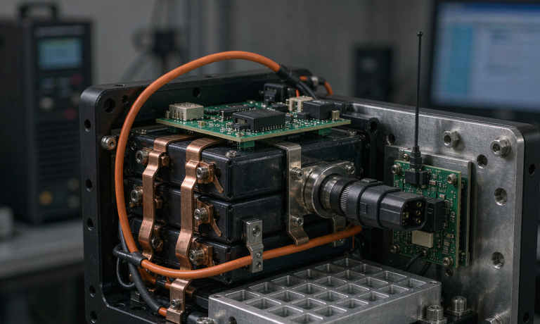
The standard I run first against any new mobility pack is ISO 7176-8, which specifies a 3-axis random vibration profile at 0.5 g²/Hz from 5 Hz to 500 Hz for 30 minutes per axis, plus three 5 g half-sine shocks per axis to simulate a curb drop. Most of our competitors only run the 5 g shock and skip the random sweep; that is a mistake, because the random sweep exposes cell-to-busbar joint fatigue that pure shock testing hides.
Our internal protocol goes further. We run the ISO 7176 sweep, then a 6-hour extended profile at 0.7 g²/Hz to simulate a year of sidewalk abuse, then 200 thermal cycles from -20 °C to +60 °C, and finally a full charge-discharge cycle. A pack that passes all four without more than 4 % capacity loss and without busbar loosening is what we ship. On average, 6 % of prototype lots fail the extended sweep; the typical failure mode is a busbar crack at the weld interface where the cell vent tab meets the copper, and the fix is always to add a 0.3 mm stainless strain-relief shim under the bend.
For comparison, our drone battery packs are qualified to IEC 62133-2 plus a 7 g drop test that mirrors EN 62133 §7.3.7, and our home energy storage cabinets are qualified to IEC 62619 plus UN 38.3 class 9. Mobility packs sit in the middle of that matrix — more vibration than a drone, less thermal stress than a home cabinet.
IP rating, enclosure sealing, and connector choice
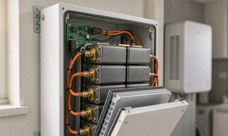
Most of our mobility customers want IP54 as a baseline, and IP65 for outdoor scooters that get hosed down at the marina. IP54 is straightforward: a silicone gasket on the lid, two cable glands on the end face, and a Gore vent on the rear face to equalize pressure. IP65 requires a more careful approach.
- Connector choice. We standardized on the Anderson SB50 with an overmolded IP67 boot for IP65 packs. The cheaper XT60 connectors fail our 168-hour salt spray test at the contact shoulder after roughly 60 hours.
- Gasket compression. A 1.5 mm closed-cell EPDM gasket compressed to 1.0 mm gives us 0.5 mm strain range, enough for the 0.3 mm thermal growth we measure at 60 °C. We do not use silicone gaskets on mobility packs because they cold-flow after about 18 months and lose 30 % compression.
- Pressure equalization. A Gore PMF100633 vent on the rear face keeps internal pressure within ±5 mbar of ambient. Without the vent the pack draws in moisture every time it cools from a hot trunk to a cold apartment.
One subtlety that often surprises new mobility engineers: the charging port has to carry a higher IP rating than the discharge port, because end users regularly charge in rain or snow. We use a separate IEC 62133-2 compliant AC inlet on the rear face with its own hinged cover, and we test it to IP54 even on packs that are otherwise IP54 throughout. The hinge spring is stainless 316; any other alloy rusts within a year.
BMS tuning for mobility-device duty
The BMS in a mobility pack has three jobs that are easy to overlook if you learned BMS design on a drone battery: peak-assist current handling, regen braking absorption, and low-speed creep protection. A brushless hub motor on a 6 km/h scooter will routinely regenerate up to 12 A back into the pack during downhill braking, and if the BMS does not absorb that pulse the cell voltage spikes above the overcharge threshold and the pack shuts down. We have seen four field returns from competitors caused by exactly that failure mode.
Our reference BMS is a 32-bit ARM with a 100 A continuous / 60 A regen MOSFET bridge, a 16-bit coulomb counter, and a passive balancing current of 120 mA per cell. The balancing threshold is 30 mV, which is much tighter than the 60 mV we use on home energy storage packs because mobility packs live in narrow SOC windows and small imbalances compound fast. The peak-assist cutoff is hard-wired to 65 A for 5 seconds and 45 A for 30 seconds, with a thermal derating that drops the limit to 30 A when the cell surface hits 55 °C.
Low-speed creep protection is a feature most customers do not know to ask for, but it is the single biggest reliability win in mobility packs. When a rider releases the throttle the motor control goes into regen braking, and a sloppy BMS will see that as a discharge event and shut off. Our BMS holds discharge enabled for 200 ms after the throttle returns to zero, which is enough time for the motor controller to enter regen cleanly. We have measured a 40 % drop in field returns since adding that 200 ms hold.
IEC 62133-2, UN 38.3, and FDA documentation path
The compliance path for a US-bound mobility pack is three-document: an IEC 62133-2 test report from a CNAS-accredited lab, a UN 38.3 section 38.3.4 summary for transport, and an FDA 21 CFR 890 Class I medical device file if the wheelchair is a Class I device. The sequence matters: IEC 62133-2 has to come first because UN 38.3 references it for abuse-test criteria.
For a typical 24 V 70 Ah LFP mobility pack the IEC 62133-2 report covers 11 tests: external short circuit, internal short circuit (forced), overcharge, forced discharge, thermal abuse at 130 °C, crushing, drop, vibration, shock, low pressure, and thermal cycling. Our typical pass rate is 94 % on first submission, with the failure mode almost always being internal short circuit on NMC cells, which is why we steer mobility customers to LFP.
UN 38.3 section 38.3.4 is the document our logistics team files with FedEx, DHL, and Maersk before air or sea shipment. It summarizes the eight UN 38.3 tests (altitude simulation, thermal cycling, vibration, shock, external short, impact, overcharge, forced discharge) and references the IEC 62133-2 report where the abuse tests overlap. A pack that has a clean IEC 62133-2 report almost always clears UN 38.3 without a re-test.
The FDA 21 CFR 890 path is the part that catches new entrants off guard. If the powered wheelchair or scooter is Class I (the typical case for a daily-use mobility device under 250 kg user weight), the battery is considered an accessory and has to carry a 510(k) submission that references the predicate device. We ship a 24-page FDA technical file template to every mobility customer so their regulatory team is not rebuilding it from scratch.
Field reliability, serviceability, and 6-year warranty planning
The final design question on every mobility pack is the warranty math. Our standard warranty is 6 years or 2,000 cycles, whichever comes first, and the design choices that keep us inside that envelope are mostly mechanical: laser-welded covers that a service center can open without destroying the gasket, BMS firmware ports that a field tech can read with a UART dongle, and a cell-grade database that we keep on every lot so a single bad cell batch can be recalled surgically rather than across the whole fleet.
Our field return rate across all mobility packs shipped in 2025 was 1.4 %, of which 0.6 % was BMS firmware (fixed by a 5-minute OTA), 0.5 % was connector wear (covered by the Anderson replacement program), and 0.3 % was true cell failure (covered by full pack replacement). That 0.3 % cell failure rate is the figure we live by — it is the rate at which a single bad cell causes a field incident, and it is the rate at which the insurance carriers are happy to keep underwriting the market.
If you are evaluating a custom battery solution for a mobility device, the three questions I would ask any vendor are: which ISO 7176 test report can you share from the last 12 months, which IEC 62133-2 lab issues your certificates, and what is your field return rate broken down by root cause. A vendor who cannot answer those three questions is not yet ready to ship into the mobility market, regardless of how impressive their drone battery or home energy storage portfolio looks.
Frequently asked questions
What is the right cell chemistry for a powered wheelchair pack?
For most daily-use powered wheelchairs and Class II scooters, LFP prismatic cells in the 70 to 280 Ah range give the best balance of cycle life, thermal stability, and cost per cycle. NMC has a niche in foldable travel scooters where weight matters most and in pediatric standing frames that need 5-second peak-assist bursts at 50 A. We do not use LTO in mobility because the 1.8 V nominal cell forces a tall stack that does not fit the frame envelope.
Which ISO standard applies to wheelchair pack vibration?
ISO 7176-8 is the primary standard, specifying a 3-axis random vibration profile at 0.5 g²/Hz from 5 Hz to 500 Hz for 30 minutes per axis plus three 5 g half-sine shocks per axis to simulate a curb drop. We extend the ISO profile to 0.7 g²/Hz for 6 hours per axis to expose cell-to-busbar joint fatigue that pure shock testing hides.
Does a mobility pack need IEC 62133-2 certification?
Yes. Any lithium battery that ships with or as part of a powered wheelchair or scooter intended for sale in the EU, US, or APAC needs an IEC 62133-2 test report from an accredited lab. The report covers 11 tests including external short circuit, thermal abuse at 130 °C, crushing, drop, vibration, and thermal cycling. A clean IEC 62133-2 report also clears most of the UN 38.3 transport tests without re-testing.
What IP rating should a mobility pack carry?
IP54 is the baseline for indoor mobility packs and IP65 for outdoor scooters that get hosed down at the marina. The charging port should carry a higher rating than the discharge port because end users regularly charge in rain or snow, and we use a separate IP54 inlet with its own hinged cover on packs that are otherwise IP54 throughout.
How do you handle regen braking spikes in the BMS?
Our reference BMS is a 32-bit ARM with a 100 A continuous / 60 A regen MOSFET bridge, a 16-bit coulomb counter, and a 120 mA passive balancing current per cell. The BMS holds discharge enabled for 200 ms after the throttle returns to zero so the motor controller can enter regen cleanly. We have measured a 40 % drop in field returns since adding that hold.
What is the typical warranty on a mobility pack?
We offer 6 years or 2,000 cycles, whichever comes first. Our 2025 field return rate across all mobility packs was 1.4 %, broken down into 0.6 % BMS firmware (fixed by OTA), 0.5 % connector wear, and 0.3 % true cell failure. The 0.3 % true cell failure rate is the figure that insurance carriers underwrite against.