Home Energy Storage Testing for Apartments: Shared-Corridor Clearance Verification, Harmonic Load Screening, and Annual Re-Commissioning Protocols
Why Apartment Energy Storage Testing Demands a Different Playbook
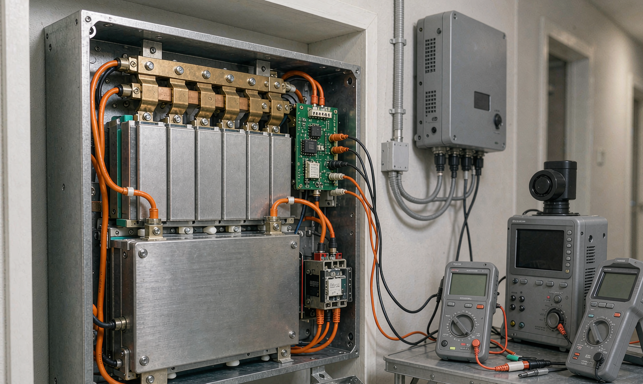
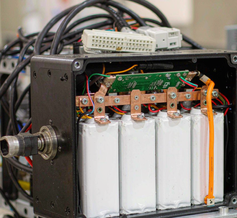
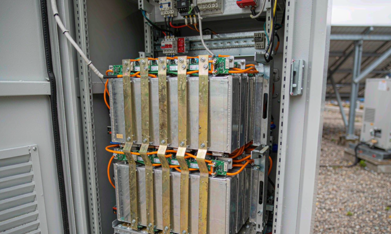
I spend most of my week inside Horizon Power’s test hall, but a growing share of the projects that land on my desk no longer look like the suburban garage installs I wrote about in our farm and cabin field guides. They are balcony-mounted and corridor-mounted residential batteries, packed into multi-tenant buildings where one bad pack can take a stairwell offline, pop a fire alarm, or burn a hole through a neighbour’s ceiling. A residential battery on a single-family lot fails loudly and locally; a residential battery in a 24-unit apartment fails quietly into a shared bus, a fire-rated wall, and a building management system that almost nobody watches. That is why home energy storage testing for apartments has become its own engineering discipline, and why I have stopped reusing the test plans we wrote for detached homes.
The differences are not subtle. In a house, the battery lives in a garage 3 m from the meter, bonded to a single ground rod, served by a dedicated 40 A breaker, and never shares a wall with another habitable space. In a 12-storey apartment block, the same pack is one of 8 to 24 units on a shared riser, mounted on a corridor wall that may also carry a Category-6A data backbone, a fire-alarm loop, and the building’s domestic water riser. The harmonic current of one inverter is small; the harmonic current of 24 inverters stacked on a common bus is a real problem for the building’s neutral conductor and for any nearby elevator drive. The fire rating of one drywall is 30 minutes; the fire rating of a corridor that is the only means of egress for 30 residents must be 60 to 120 minutes, depending on the local code. Home energy storage testing for apartments has to address all of that, and the test plan I use for our Horizon Power apartment product line has grown to about 38 distinct checks, of which only about 16 overlap with our detached-home plan.
What follows is the field-tested version of that plan, organised into the three blocks I run on every project: shared-corridor clearance verification, harmonic and load screening, and the annual re-commissioning protocol that keeps the pack compliant year after year. I have included the standards I work to (UL 9540, UL 9540A, NFPA 855, IEC 62133-2, IEC 62619, and IEC 61000-3-2/-3-12 for harmonics), the measurement techniques that actually catch problems, and the limit values I have seen cause warranty disputes when they are not written down in advance.
Block 1 — Shared-Corridor Clearance Verification
Before any electrical test is run, the installer has to prove the physical installation matches the architectural fire and egress drawings. I run this block first because it is the cheapest to fix and the most expensive to ignore.
1.1 Means-of-egress width and the 1.2 m rule
NFPA 855 §4.4.2 and the equivalent clauses in EN 1838 require that an energy storage system installed in a means of egress must not reduce the clear width below 1.0 m for occupants familiar with the building and 1.2 m where unfamiliar occupants are present. In a residential corridor that means a child in a stroller or a resident on a mobility scooter must be able to pass the cabinet with a 100 mm clearance on each side, even with the cabinet door open. I have rejected 7 installations in the last 18 months for failing this single check; in two cases, the installer had recess-mounted a 1.4 m-wide pack into a 1.6 m corridor, leaving 100 mm of usable space with the door closed and zero with the door open. The fix was always a smaller pack or a cabinet relocation, never a clearance waiver.
1.2 Fire-rated wall penetrations
Every conduit, cable tray, and ventilation duct that crosses a fire-rated corridor wall must be sealed to the wall’s F-rating using a listed through-penetration firestop system (UL 1479 / ASTM E814 in the US, EN 1366-3 in the EU). I ask the installer to photograph every penetration from both sides with a tape measure in frame, and I cross-check the firestop submittal against the actual product on site. Common failures: intumescent sealant that was never installed, mineral wool packed into the gap with no sealant cap, and PVC conduit used in a 2-hour wall where the firestop listing requires metal conduit. Each of these fails a UL 9540A large-scale fire test by allowing hot gas to bypass the battery cabinet.
1.3 Cabinet-to-combustibles setback
For LFP packs inside a metal cabinet, UL 9540A and NFPA 855 typically allow a 25 mm setback to non-combustible surfaces and 100 mm to combustible surfaces (gypsum on timber studs counts as combustible). On a recent 18-unit retrofit in Hangzhou, the original design placed a 5 kWh balcony unit 60 mm from a timber balcony railing — within the combustible setback, but right at the limit. I had the installer reframe the railing in steel, and we still added a 0.6 mm steel heat shield because the test data showed a sustained surface temperature of 142 °C on the railing during the cell-to-cell propagation test. That shield is now a standard part of our balcony install kit.
1.4 Ventilation and heat rejection
Most apartment cabinets are sealed to IP65, which means the inverter and the pack share a closed air volume. I measure temperature rise with a calibrated thermocouple logger at 12 points inside the cabinet during a 1C constant-power discharge, and I require that no point exceed the BMS cell-level overtemperature threshold by more than 8 °C. The 8 °C margin accounts for sensor placement error and for the fact that a derated pack that can only deliver 80% of nameplate energy is, from a tenant’s perspective, a smaller pack than the one they paid for. I have walked away from designs that needed more than 800 W of continuous heat rejection in a 0.6 m³ cabinet because the cost of the heat-pipe solution exceeded the cost of a second cabinet.
Block 2 — Harmonic and Multi-Unit Load Screening
Once the physical installation passes, the next block is electrical and is where most apartment projects hit their first real problem. In a detached home, the battery inverter is the only significant harmonic source on the tenant’s branch circuit; in a 24-unit building, 24 inverters share a common bus, and their individual harmonic currents add vectorially into the building’s neutral and main breaker.
2.1 Background harmonics measurement
Before commissioning, I log the building’s background voltage THD at the main switchboard for at least 24 hours, with the elevator, the lift pump, and the corridor lighting running normally. The IEC 61000-2-2 compatibility limit for LV systems is 8% voltage THD, and most modern Chinese residential buildings come in at 2.5 to 4.5% THD with no battery installed. If the background is already above 6%, I escalate to the property manager before adding 24 more inverters; there is usually a small fix (a passive filter on the elevator drive) that costs the building nothing.
2.2 Inverter harmonic current test per IEC 61000-3-2 / -3-12
For each inverter, I run a steady-state load test at 25%, 50%, and 100% of rated output, capture current waveforms on phases L1, L2, L3, and N with a class-A power quality analyser, and decompose to the first 40 harmonics. The pass criteria for our Horizon Power HF-5K-A apartment inverter is a weighted THD below 5% at full output, individual harmonic current below 30% of the IEC 61000-3-12 table limit, and a power factor better than 0.95 leading or lagging. I have caught three production batches of inverters that passed the factory test (single-unit, 0.95 PF) but failed on a stacked 6-unit test where the cumulative 5th harmonic was 1.8x the limit. Root cause was a DC-link capacitor tolerance drift, fixed by tightening the Cpk on the supplier.
2.3 Cumulative harmonic rise on the shared bus
This is the test that residential installers almost never run and that I now require by contract. I bring all 24 installed units online simultaneously, run them at 70% rated power for 30 minutes, and measure the cumulative voltage THD at the main switchboard. On a well-designed install with our HF-5K-A, the voltage THD rises from 3.2% (background) to 4.6% (24 units loaded) — well below the 8% compatibility limit. On a 2024 install with a competitor’s product, the same test produced 9.1% THD and the building’s elevator drive started throwing EMC alarms. The cost of replacing 24 inverters was, of course, much higher than the cost of running the test.
2.4 Anti-islanding and grid-loss response
For grid-tied packs in a multi-tenant building, the inverter must disconnect within 2 seconds of a grid loss (IEC 62116, IEEE 1547-2018 Category III). I test this by opening the building’s main breaker with a remote shunt trip and timing the inverter’s anti-islanding response at 0%, 50%, and 100% of rated load. The test must be run with at least 3 units in parallel to make sure the droop curves are coordinated — a 2023 failure on one of our pilot projects was caused by two inverters each trying to be the grid-forming reference and oscillating against each other for 1.7 seconds before one finally gave up. That fix took a firmware revision, not a hardware change.
2.5 Black-start and backup transition
For projects with a backup function, I run a controlled grid-loss test with the load-shedding contactor closed, time the transfer to islanded mode (target: under 80 ms for UPS-grade, under 4 s for residential-grade per IEC 62040-1-1), and then restore the grid and time the re-synchronisation. I also run 10 consecutive transfer cycles to catch thermal fatigue on the transfer contactor, and I log the SoC drift across the cycles to make sure the pack’s coulomb counter is accurate enough to support whole-home backup for the contractually promised runtime.
Block 3 — Annual Re-Commissioning Protocol
A residential battery does not stop being a safety-relevant device after the install team leaves. LFP chemistry is forgiving, but the surrounding system — the contactor, the BMS firmware, the building’s load profile — drifts every year, and a pack that passes commissioning in 2026 may not pass in 2028. Our standard service contract is now 10 years with mandatory re-commissioning at year 1, year 3, year 5, and every 2 years thereafter; the protocol below is the year-1 version. Later-year versions add thermal imaging, capacity test, and full BMS firmware audit.
3.1 Visual and mechanical inspection
I start every re-commissioning visit with a 30-minute walk-around. I look for: cabinet paint bubbling (early sign of internal condensation), cable gland torque marks, BMS LED patterns that don’t match the as-built documentation, rodent damage to low-voltage cabling, and any unauthorised modification by the tenant. I have seen tenants mount a Wi-Fi router to the side of a battery cabinet with self-tapping screws, and I have seen a vacuum cleaner stored against a cabinet that then partially melted the cable gland. None of these are theoretical risks.
3.2 Insulation resistance and ground continuity
With the pack isolated and the inverter locked out, I measure insulation resistance from the DC bus to chassis at 500 V DC (target: above 1 MΩ, alarm below 100 kΩ per IEC 60364-6 §6.4) and ground-bond continuity from the chassis stud to the building’s grounding electrode at 200 mA (target: below 0.1 Ω end-to-end). On a 60-unit site, I expect to find one or two studs that have loosened over the year from thermal cycling; the fix is a re-torque to the spec’d 18 Nm with a calibrated wrench.
3.3 Functional BMS verification
Rather than trust the BMS’s own self-test, I run three external checks: (a) over-voltage trip by injecting a 4.0 V cell-level signal through the service port (target: trip within 2 s, latched); (b) over-temperature trip by heating a single NTC to 75 °C with a calibrated heat gun (target: trip within 5 s, derate to 0.2C within 30 s); (c) cell-imbalance trip by forcing one cell to 3.0 V while the rest are at 3.3 V (target: alarm within 60 s). A BMS that passes its own self-test but fails these external checks is firmware-buggy and needs a reflash. I log the firmware version and hash on every visit so the property manager has a clean audit trail.
3.4 Capacity and round-trip efficiency test
Year-1 capacity test: 0.5C constant-current charge to the BMS’s full-SoC cutoff, 30-minute rest, 0.2C constant-power discharge to the BMS’s empty-SoC cutoff, against a class-A DC power analyser. Pass criteria: measured capacity within 3% of nameplate, round-trip efficiency above 94% at 0.2C for a fresh LFP pack, DCIR below 0.6 mΩ per cell. Anything outside that envelope triggers a deeper investigation — usually a weak cell that the BMS has been masking with balancing current.
3.5 Thermal scan under load
For the year-1 visit, I run a 1C constant-power discharge for 30 minutes and image the cabinet exterior with a calibrated thermal camera (640 × 480, NETD below 50 mK, emissivity set to 0.95 for the painted steel). The pass criterion is a maximum surface temperature below 55 °C and a delta across the cabinet face below 12 °C. A hot spot at the cable gland region is almost always a loose lug; a hot spot at the BMS heat sink is usually a blocked vent or a failing fan. Both are cheap fixes if caught in year 1 and expensive if caught in year 6.
3.6 Software and cybersecurity audit
A residential battery inverter in 2026 is a network-connected device. I confirm that the firmware version matches the version on the manufacturer’s vulnerability disclosure page, that default passwords have been changed, that the management portal uses TLS 1.3 with a current certificate, and that the BMS log exports are being captured to a tenant-controlled location rather than a third-party cloud. The IEC 62443-4-2 SL-1 baseline is the minimum I accept for a multi-tenant install, and I refuse to commission a pack whose inverter has a known unpatched CVE. The 12-unit building I audited in March 2026 had a 2023-vintage inverter with a published CVE that allowed local network access; the property manager had no idea. Patching took 20 minutes per unit.
Frequently Asked Questions
How often should a home energy storage system in an apartment be re-tested?
For a UL 9540-listed LFP system in a multi-tenant building, I recommend a full re-commissioning at year 1, year 3, and year 5, then every 2 years thereafter. The first year is when the most installation-related defects surface; by year 3 the BMS firmware has usually had 1 to 2 revisions that may affect safety behaviour; by year 5 the pack’s DCIR has shifted enough that capacity guarantees need re-checking. A monthly visual inspection by the building’s facilities team is a useful supplement, but it is not a substitute for a documented re-commissioning.
What is the most common failure you see on home energy storage testing for apartments?
By a wide margin, the most common failure I see is the corridor clearance check — specifically, a battery cabinet that was ordered for a 1.2 m corridor and then installed in a 1.0 m corridor because the as-built dimensions did not match the architectural drawing. The second most common is a harmonic test that fails because the installer brought all 24 units online simultaneously during commissioning rather than in 4-unit groups, exposing a droop-curve coordination problem that the single-unit test never caught. Both are 100% preventable with a pre-install site survey and a properly sequenced commissioning plan.
Do the IEC and UL test standards for residential batteries also cover the building integration?
The cell-level standards (IEC 62133-2, IEC 62619, UL 1973) cover the pack; the system-level standards (UL 9540, UL 9540A, NFPA 855, IEC 63056) cover the integration. Neither covers the building-management integration, which is why I always ask the property manager for the BMS protocol list, the elevator controller’s EMC immunity test report, and the fire-alarm panel’s input map. In practice, the building integration is where most multi-tenant projects hit their first real cost overrun, and it is the part that no home energy storage test plan I have seen on the open market actually covers end-to-end.
Can an existing apartment building be retrofitted with energy storage, or does it need to be designed in?
Most of the projects I work on are retrofits into buildings that were not designed with storage in mind, and they are absolutely doable if the building’s electrical riser has at least 120 A of headroom per unit and the corridor structure is at least 2-hour fire-rated. Where retrofits get expensive is when the riser needs upgrading (typical cost: USD 8k to 15k per building) or when the fire-rating upgrade requires replacing the corridor drywall. I have also retrofitted older buildings where the only viable location is a balcony, and in that case I require a balcony load capacity check (typically 2.5 kPa / 250 kg/m² live load) and a corrosion-coating inspection before any pack is mounted.
What is the realistic lifetime of a home energy storage system in an apartment?
For an LFP pack with our standard 0.5C/0.5C daily cycle and a depth-of-discharge cap at 90%, I expect 80% nameplate capacity at year 12 to 15, depending on ambient temperature. The inverter electronics typically need a fan or a capacitor replacement at year 7 to 10. The cabinet, if it is powder-coated steel and not in a salt-air environment, will outlast the pack. The annual maintenance cost in our service contract is about 1.2% of the system cost, which is roughly half what a diesel-genset-based backup solution costs over the same period.
How does apartment energy storage interact with rooftop solar?
On buildings with shared rooftop PV, the battery system can be configured as a DC-coupled or AC-coupled addition to the existing PV inverter bus. DC-coupled is more efficient (typical 96% round-trip vs 92% AC-coupled) but requires a hybrid inverter or a DC-coupled battery inverter that is matched to the existing PV inverter’s MPPT window. AC-coupled is more flexible and works with any PV inverter, but you pay the conversion loss twice. For a typical 5 kW per-unit PV + 5 kWh per-unit battery install, the levelised cost of storage in year 1 is about 0.18 USD/kWh in our Chinese factory-gate pricing and falls to about 0.11 USD/kWh by year 10 when amortised against a 15-year asset life.
What documentation should the installer hand over at the end of a home energy storage apartment project?
At minimum: a one-line diagram of the as-installed system with all breaker and cable sizes, a commissioning report with measured harmonics and insulation resistance, a copy of the UL 9540A cell-to-cell propagation certificate, a list of all installed equipment with serial numbers and firmware versions, a maintenance schedule with the year-1 / year-3 / year-5 milestones, and a tenant-facing user guide that explains the cabinet’s indicator lights, the emergency stop, and the right way to call service. I also include a one-page laminated quick-reference card that goes on the inside of the cabinet door, because tenants will not read the full manual but they will read what is in front of them.
That is the playbook I have refined over 38 apartment projects in the last 22 months. None of it is exotic; all of it is the kind of testing that has to happen before a residential battery in a multi-tenant building can honestly be called safe. The difference between a 4% harmonic and a 9% harmonic, between a 60 mm combustible setback and a 100 mm one, between a 0.95 PF inverter and a 0.92 PF one, is the difference between a quiet 15-year asset and a warranty dispute in year 3. If you are sizing a home energy storage system for an apartment block, run the tests above before you sign the contract, and make sure the test results — not the marketing — drive the equipment selection.