Battery Solution for Autonomous Mobile Inspection Robots: Pack Sizing, Dock Charging and BMS Design Guide
I have spent the last decade specifying cells and packs for machines that are expected to work the night shift without a driver, and autonomous inspection robots are the most demanding of the lot. Not because the power is extreme — a mid-size autonomous mobile robot rarely draws more than a few hundred watts — but because nobody is there to notice when the battery is tired, mis-charged, or quietly drifting out of balance. When a patrol robot stops in a substation corridor at 03:00, the inspection round is lost, the client is unhappy, and the root cause is almost always energy: an undersized pack, a dock that misses contact, or a state-of-charge estimate that lied.
This guide is written for the engineers and procurement teams building or buying inspection robots — substation patrol units, warehouse aisle scanners, tunnel and pipe crawlers, perimeter-security rovers. I will walk through how I size a battery solution for inspection robots from a real duty cycle, why I almost always land on LiFePO4 in a 48 V architecture, what the mechanical and thermal integration has to survive, how the BMS and charging dock should be specified, which standards actually get invoked in a compliance review, and the acceptance test sequence I run before a pack goes into a fleet.
What an inspection robot actually demands from its battery
The first mistake I see in incoming RFQs is a single number: “we need 2 kWh.” A robot is not a bucket of energy. It is a set of loads with very different dynamics, and the pack has to satisfy all of them simultaneously.
In a typical indoor inspection robot I break the load into four buckets:
- Compute and perception. An industrial PC plus a 2D/3D LiDAR, two or three cameras, an IMU and a wireless radio stack sits between 30 W and 120 W depending on whether inference runs on-board. This load is nearly constant and it never sleeps.
- Traction. Two differential drive hubs average 100–250 W on flat concrete, but peak 600–900 W during acceleration, dock approach and ramp climbs. Peak matters more than average for voltage sag and BMS trip margin.
- Payload transients. A pan-tilt camera, a gas sniffer pump, a robotic arm or an ultrasonic thickness gauge adds 5–40 W with sharp edges.
- Hotel load. The BMS, contactors, Ethernet switch and LED beacons quietly eat 5–15 W all shift long, including while parked.
That produces a duty cycle with a steady 150–250 W baseline and short 2–5 s traction peaks two to four times higher. Size energy on the average; size cells, busbars and BMS trip thresholds on the peak.
Sizing the pack from a real duty cycle
Here is the arithmetic I use, with a worked example from a substation patrol robot we supported in 2024.
The robot had to run a 10-hour shift, cover 14 km, and complete 42 inspection stops. Measured average draw was 205 W, with 780 W traction peaks of 3 s. Peak season ambient inside the switchyard enclosure reached 42 °C; winter nights fell to −8 °C.
Step one, energy:
- Raw energy = 205 W × 10 h = 2,050 Wh.
- Depth of discharge: I design to 80 % usable, not 95 %, because the last 10 % of an LFP discharge curve collapses fast in cold weather and I want range margin. 2,050 / 0.80 = 2,563 Wh usable.
- System losses: BMS, DC-DC conversion and wiring eat 5–8 %. Divide by 0.93 → 2,755 Wh.
- Aging margin: I require the pack to still deliver a full shift at end of life, so I add 15 % for capacity fade. 2,755 / 0.85 = 3,240 Wh nameplate.
Step two, configuration. At 48 V nominal that is 3,240 / 51.2 ≈ 63 Ah, so 48 V / 60 Ah commercial, or a 16S arrangement of 60–65 Ah prismatic LFP cells. I chose 48 V over 24 V deliberately: at 780 W peak, a 24 V pack pulls 32 A while 48 V pulls 16 A. Halving current quarters resistive loss in the harness and dock contacts, and lets me use a smaller, cooler contactor.
Step three, peak verification. The 3C-rated cells gave 180 A against a 16 A peak, but the real check is DCIR: 18 mΩ at 25 °C, 47 mΩ at −5 °C. Cold-weather sag at 780 W was therefore 780/48 × 0.047 ≈ 0.8 V, about 1.6 %, comfortably inside the 44 V lockout of the drives. The same pack at 24 V would have sagged 3.2 % and nuisance-tripped on every ramp after two years of resistance growth.
Chemistry and cell format: why I keep landing on LiFePO4
Three chemistries show up in inspection-robot RFQs, and the trade-offs are stable:
- LiFePO4 (LFP). 3.2 V nominal, cell-level 160–180 Wh/kg, pack-level 110–135 Wh/kg once you add enclosure, BMS and structure. 3,000–6,000 cycles to 80 % capacity at 80 % DoD, thermal runaway onset around 270 °C, and a very flat 3.25–3.30 V plateau that makes voltage-based SoC estimation poor but makes the discharge curve beautifully stable for motor drives.
- NMC (LiNiMnCoO2). 3.6–3.7 V nominal, cell 240–270 Wh/kg, pack 160–190 Wh/kg. Roughly 1.4× the energy per kilogram, 1,500–2,500 cycles, thermal runaway onset 150–210 °C. Worth it only when mass is the binding constraint — a climbing or pipe-crawling robot, not a wheeled floor unit.
- LTO (Li4Ti5O12). 2.4 V nominal, 60–90 Wh/kg, but 15,000–20,000 cycles and −30 °C charging at 1C. I specify it for robots in cold storage, LNG terminals and Nordic substations where a heated pack is impractical.
For a wheeled indoor or outdoor inspection robot, the energy density advantage of NMC is worthless: the robot needs ballast mass for traction anyway, and the chassis has room. LFP wins on cycle life, abuse tolerance and the fact that a 16S LFP pack sits inside the 60 V SELV limit, which simplifies the safety file considerably.
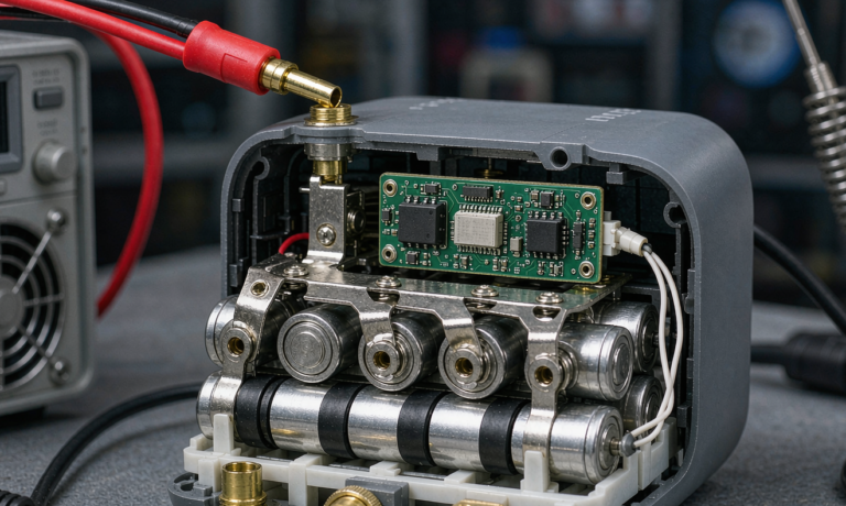
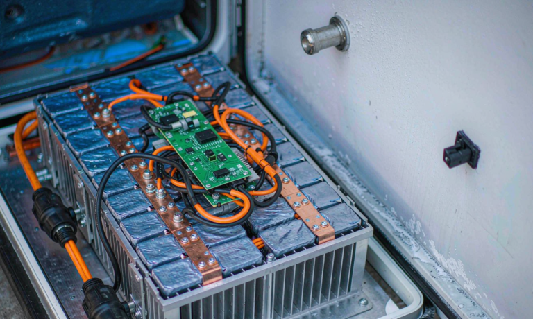
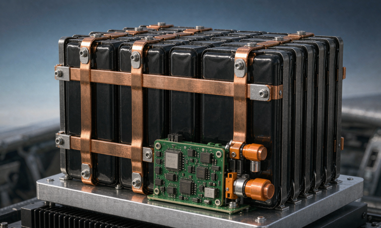
On format, prismatic aluminium-can cells in the 50–100 Ah range are my default above 1.5 kWh: fewer parallel strings, fewer welds, easier clamping, better heat spreading. Below 1 kWh, or where the pack must fit an odd cavity, 21700 cylindrical cells give geometric freedom at roughly 8–12 % more internal resistance and far more weld joints to validate.
Mechanical and thermal integration
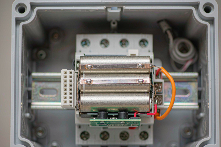
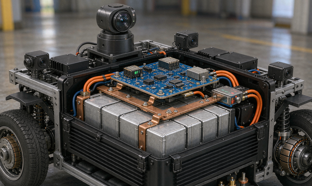
A robot pack lives a harder mechanical life than a stationary battery solution: expansion joints, cable trays, grated flooring, and a low mounting position where it collects water and dust.
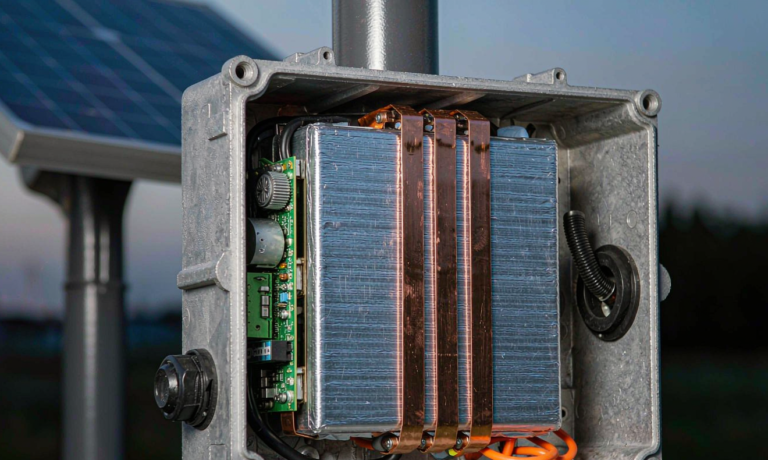
- Ingress protection. IP54 for indoor warehouse units; IP65 minimum outdoors, preferably IP66 with a breathable hydrophobic vent. A sealed pack that breathes through its connector will pull in condensation overnight — I have torn down three that died this way.
- Vibration and shock. I qualify to IEC 60068-2-64 random vibration, 5–500 Hz at 0.5–1.0 g RMS for 8 h per axis, plus IEC 60068-2-27 shock at 15–30 g / 11 ms. Prismatic stacks need 5–10 % pre-compression; a stack that can rattle frets its busbar welds loose within a few thousand hours.
- Thermal path. Natural convection through the enclosure wall covers up to about 0.15 C continuous. Beyond that, or above 40 °C ambient, add a 3–5 mm gap-pad path to an aluminium cold plate tied to the chassis. Keep cells under 45 °C charging and 55 °C discharging — every 10 °C above 30 °C roughly halves calendar life.
- Cold operation. Charging below 0 °C plates metallic lithium and permanently consumes inventory. My BMS blocks charge below 2 °C, resumes at 5 °C, and uses a 40–80 W film heater to recover. Discharge to −20 °C is fine at reduced rate, at 70–80 % of nominal capacity.
BMS, state of charge and safety logic
The BMS on an inspection robot does three jobs that are frequently conflated: protection, estimation, and fleet telemetry.
Protection. Primary protection must be hardware, not firmware. I specify an analogue front-end with independent over-voltage (3.65 V/cell for LFP), under-voltage (2.5 V/cell hard, 2.8 V warning), over-current (typically 2× continuous, 5× for 100 ms) and a secondary thermal fuse plus a pyro-free mechanical contactor that opens on a latched fault. Charge and discharge MOSFETs or contactors should be redundant: one device that welds shut must not create an uncontrolled path.
Estimation. LFP’s flat OCV-SoC curve — about 3 mV per percent SoC in the mid-band — makes pure voltage SoC useless, with errors up to 15 %. I run coulomb counting with a 0.5 % current-shunt accuracy budget, re-anchored by OCV after 30–60 min of rest, and corrected by a temperature-dependent capacity model. Done properly this delivers 3–5 % SoC error across the shift, which is what you need for the robot to decide whether it can finish a route or must return to dock.
Telemetry. Every pack I ship logs per-cell voltage, current, three thermistor channels, SoC, SoH and fault history to non-volatile memory at 1 Hz over CAN, mirrored to the fleet server. When a robot fails a route, the pack log is the first thing I read — and the SoH trend turns replacement from a calendar guess into a scheduled event.
If the robot works around people, the stop function must meet ISO 13849 PLd or IEC 62061 SIL 2, which means the BMS cannot be the only thing holding the contactor closed: the safety chain — e-stop, bumper, scanner — has to break the main power path independently of firmware.
Charging strategy: dock design and opportunity charging
Autonomy is only as good as the dock. In my experience more inspection-robot downtime comes from failed docking than from cell aging.
- Conductive dock contacts. For 48 V / 60 Ah packs I use silver-plated copper pads rated 100–200 A with contact resistance below 0.5 mΩ, spring travel of 8–12 mm, and a specified misalignment tolerance of ±10–15 mm lateral and ±3° yaw. Wipe the pads during engagement to break oxide; specify 10,000–30,000 mating cycles and a cleaning interval.
- Opportunity charging. A 10-hour shift with a 60 Ah pack can run entirely on a single overnight charge, but fleets that run two shifts need top-ups. Charging at 0.5 C to 80 % then tapering takes about 70 min; three 15-minute 1C bursts during idle periods add roughly 40 % capacity without meaningful cycle penalty, provided cell temperature stays under 40 °C.
- Battery swap. For 24/7 operations, a 30-second swap with a hot-swap controller beats fast charging on both uptime and cycle life. Budget for a second pack per robot and a charging cabinet with per-slot balancing and fire separation.
- Inductive charging. 1–3 kW wireless pads remove all contact wear and allow sealed enclosures with zero exposed conductors — excellent for washdown or explosive atmospheres. Accept 88–93 % grid-to-battery efficiency versus 94–97 % for conductive, and align coil-to-coil within 10 mm.
Whatever the method, the charger must be a proper CC/CV unit with temperature-compensated voltage and a genuine 0.05 C termination. Cheap lead-acid-replacement chargers that float LFP at 13.8 V equivalent will slowly overcharge and gas the cells.
Compliance and transport
An inspection robot battery solution rarely fails a customer audit on performance; it fails on paperwork. This is the list I build into every design review:
- UN 38.3 — T1 altitude, T2 thermal, T3 vibration, T4 shock, T5 external short, T6 impact/crush, T7 overcharge, T8 forced discharge. Required for any air or sea shipment.
- IEC 62133-2 — safety of sealed secondary lithium cells and batteries for portable applications; still the baseline most buyers ask for.
- IEC 62619 — the standard that actually fits industrial robots: safety requirements for secondary lithium cells and batteries for industrial applications, including propagation resistance and BMS functional safety.
- IEC 62620 — performance and endurance testing for industrial cells.
- UL 1973 — batteries for stationary and motive auxiliary power, the usual North American ask; UL 2271 applies to light electric vehicle batteries and is sometimes invoked for small AGVs.
- ISO 3691-4 and RIA 15.08 — driverless industrial truck and AMR safety; these drive the e-stop and protective-stop behaviour around the pack.
- IEC 60204-1 — electrical equipment of machines, governing the disconnect and protection devices.
- Charger standards — IEC 60335-2-29 or UL 1564 for industrial battery chargers, plus EMC under EN 61000-6-2/-6-4 and FCC Part 15 if the dock radiates.
If the robot works in an explosive atmosphere — refineries, grain terminals, paint shops — add ATEX/IECEx 60079 consideration, which usually pushes you to a sealed, potted pack with an intrinsically limited energy budget.
Acceptance testing before the pack enters a fleet
I do not release a custom battery solution for inspection robots until it has passed this five-step sequence at pack level, not just cell level:
- Insulation and hipot. 500 V DC, insulation resistance above 1 MΩ between the high-voltage bus and the chassis — I reject below 10 MΩ on a new pack.
- Cell balance verification. Charge to 100 %, rest 2 h, then measure per-cell spread. Anything above 30 mV on a fresh LFP pack indicates a bad weld, a mismatched cell, or a balancing resistor that is not doing its job.
- Capacity confirmation. 0.2 C discharge to cutoff at 25 °C must return at least 95 % of nameplate; repeat at 0 °C and 40 °C to characterise the operating envelope the fleet software will rely on.
- Peak and protection test. Apply the real 3 s traction peak and confirm bus sag stays within the drive controller window; then bench-trip every protection threshold, including a deliberate short across the contactor to verify it opens and latches.
- Dock endurance. 500 engagement cycles with ±10 mm intentional misalignment, logging contact resistance drift; reject if it grows more than 20 %.
Add a 30-day field soak on two pilot robots before fleet rollout. The failure modes you cannot simulate — cable chafe at the harness grommet, dock pad contamination, condensation after a cold night — all show up in the first month.
Frequently asked questions
How long should an inspection robot run on one charge?
Design for a full shift plus 25 % margin. In practice that means 8–12 h for a single-shift fleet at 150–250 W average draw, which lands on a 2.5–3.5 kWh LFP pack. If your robot cannot finish its longest route with 25 % remaining at end of life, the pack is undersized.
LiFePO4 or NMC for an autonomous inspection robot?
LFP in almost every wheeled case: 3,000–6,000 cycles, runaway onset near 270 °C, and a 16S pack that stays under the 60 V SELV threshold. Choose NMC only when mass is the binding constraint — climbing robots, pipe crawlers, or anything that has to be carried by a person.
Why does my robot’s state-of-charge estimate jump around?
Because LFP’s open-circuit voltage changes only about 3 mV per percent of SoC in the mid-band, so voltage-only estimation carries 10–15 % error. You need coulomb counting on an accurate shunt, re-anchored by OCV after a rest period and corrected for temperature, to land inside 3–5 %.
Can an inspection robot charge outdoors below freezing?
Not safely without a heater. Charging LFP below 0 °C plates metallic lithium on the anode and permanently reduces capacity. My BMS blocks charge under 2 °C, resumes at 5 °C, and uses a 40–80 W film heater or self-heating pulse to get there. Discharging down to −20 °C is acceptable at reduced rate.
What is more reliable, contact docking or wireless charging?
Conductive pads are 94–97 % efficient and cheap, but they wear, oxidise and are the number one cause of failed recharges in the field. Inductive pads run 88–93 % efficient and remove all moving contact, at higher cost and with tighter alignment. For dusty or washdown environments I now lean inductive; for clean indoor fleets, well-specified silver-plated contacts with a cleaning schedule remain the better value.
How often should inspection robot packs be replaced?
Track state of health from the pack log rather than guessing by date. Plan replacement when measured capacity falls below 80 % of nameplate or DCIR grows more than 50 % from its baseline. At one shift per day on LFP that is typically 8–10 years; at two shifts with opportunity charging, 5–6 years.
Can one battery design cover a whole fleet of different robots?
Partly. Standardise the cell, the BMS platform, the communication protocol and the dock interface, then vary the series/parallel count and enclosure shape per model. That approach keeps your spare inventory and compliance file to one family while still fitting each chassis — the same principle we apply to any custom battery solution before it goes into series production.