Sodium-Ion Battery Grid Interconnection and Inverter Sizing
When a customer asks me to size a grid-tied sodium-ion battery system, the inverter is almost never the first thing I calculate. The first thing is the interconnection standard, because that single document dictates how much power the utility will let you export, how fast your inverter must trip off the grid during a disturbance, and which safety listings it must carry before it ever earns a commissioning sign-off. I am Karl Huang, Senior lithium battery Engineer at Horizon Power, and over the last decade I have commissioned behind-the-meter and front-of-meter storage across three continents. Sodium-ion has changed the economics of stationary storage, but it has not changed the rulebook that governs how a battery talks to the grid.
Why Interconnection Rules Decide Your Inverter
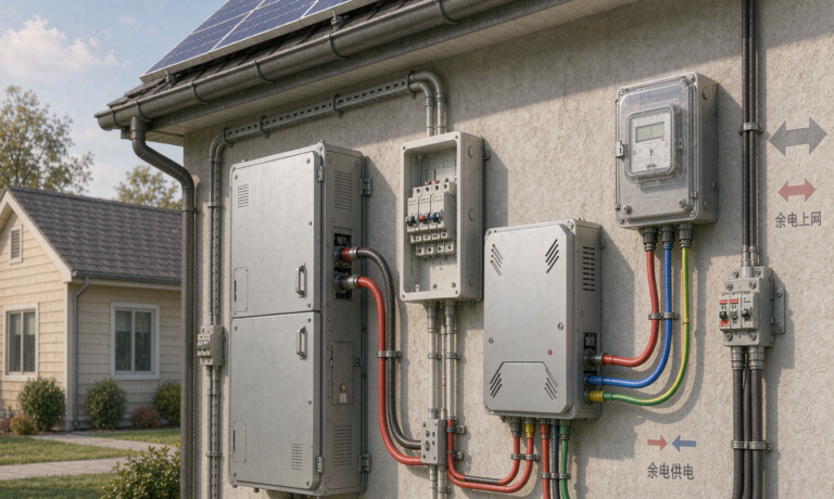
In North America the spine of any grid-tied storage project is IEEE 1547-2018, the standard that defines how distributed energy resources connect to the utility grid. A sodium-ion system is treated exactly like any other DER: it must ride through voltage and frequency disturbances, it must cease to energize a dead grid within two seconds of islanding, and it must respond to volt-var and frequency-watt commands from the operator. Under IEEE 1547 the inverter itself needs a listing to UL 1741 Supplement B (UL 1741 SB) for intentional islanding control, or Supplement A (UL 1741 SA) for more advanced grid-support functions. I always tell clients to specify SB as the floor and SA where the utility offers a feed-in tariff that rewards reactive support.
On the product side the power conversion system must carry IEC 62109 for safety of power converters and IEC 62477 for the broader power electronic converter systems, plus FCC Part 15 Class A for conducted and radiated emissions in an industrial setting. In the European market the equivalent path runs through IEC 62109-1 and IEC 62109-2, with grid behavior covered by EN 50549 and the pertinent national grid code. None of these standards care whether your cells are lithium or sodium. They care about what the box does at the point of common coupling.
Sizing the Power Conversion System to the Sodium Pack
The single most common mistake I see is sizing the inverter to the battery’s energy, not its power. A sodium-ion pack rated at 500 kWh might only be allowed to charge or discharge at 0.5C, which means the continuous power it can deliver is 250 kW. If you bolt a 500 kW inverter onto that pack, the top half of the inverter’s rating is hardware you paid for but can never use. I size the PCS to the maximum sustained C-rate of the cells, then add a margin for motor starting or transformer inrush if the load profile demands it.
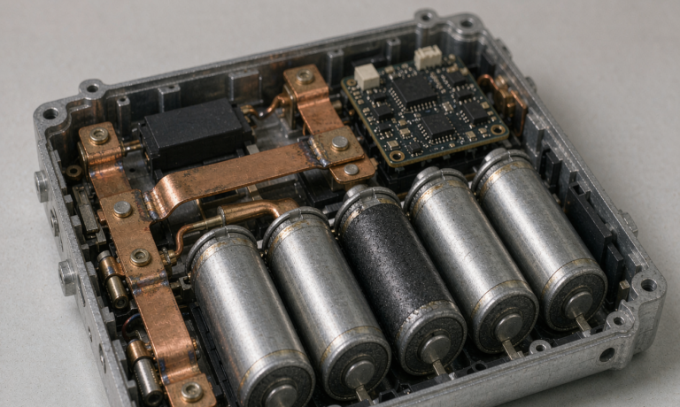
Sodium-ion cells today sit in a wider voltage window than many engineers expect. A typical prismatic sodium-ion cell runs from about 2.0 V at empty to roughly 3.95 V at full charge. A 200 V nominal string therefore swings between roughly 160 V and 316 V, and the PCS must track that band without leaving its maximum power point. I always request the cell supplier’s end-of-discharge voltage curve before I lock the string count, because the inverter’s DC bus minimum determines how many series cells you need to keep the converter in regulation down to 10 percent state of charge.
Isolation monitoring is another parameter the inverter must handle for a sodium-ion string. Because the DC bus floats relative to earth, I specify a ground-fault detection threshold of 100 kiloohm to 500 kiloohm depending on system voltage, and I confirm the PCS opens the contactor within the time required by IEC 62477 when a fault appears. This is standard for any high-voltage battery, but it is worth calling out because it is one of the few places where the larger sodium enclosure actually changes the wiring plan rather than just the footprint.
Power Quality: THD, Power Factor, and Ride-Through
Utilities are unforgiving about power quality. IEEE 1547 limits current total harmonic distortion to 5 percent for most interconnections, and many regional grid codes tighten that further at the point of common coupling. A well-designed sodium-ion PCS with a silicon carbide stage and a properly damped LCL filter will sit at 2 to 3 percent THD, which gives me headroom during weak-grid conditions. I have seen cheap inverters that were fine in the lab exceed 8 percent THD the moment they fed a high-impedance rural feeder, and that is how a perfectly good battery gets a cease-and-desist from the utility.
Power factor is the next lever. Most grid-tied inverters can be configured anywhere from 0.8 leading to 0.8 lagging, and a sodium-ion system providing volt-var support will usually operate near unity during discharge and absorb reactive power during the evening peak. Ride-through is the third: the inverter must stay connected through shallow voltage sags (LVRT) and brief over-voltage events (HVRT) for the durations spelled out in the local grid code, typically a few hundred milliseconds to a couple of seconds. I verify this in commissioning with a programmable grid simulator rather than trusting the datasheet.
Sodium-Ion Specifics That Change the Math
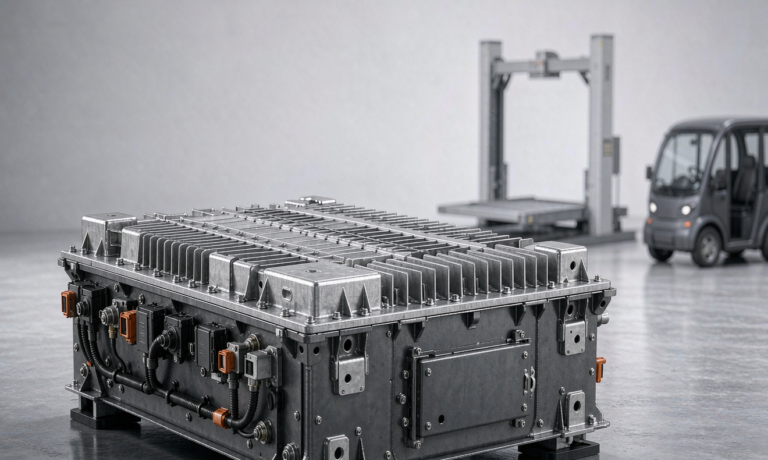
Sodium-ion trades some energy density for other advantages, and that trade has a direct effect on inverter sizing. At the pack level a sodium-ion system needs roughly 20 to 40 percent more volume than an equivalent lithium battery pack for the same kilowatt-hour rating, so the enclosure and the DC cabling get larger, but the PCS rating is unchanged because power is power. What does change is round-trip efficiency: sodium-ion today returns about 85 to 90 percent at the pack, a few points below a good lithium iron phosphate system, so I size the inverter’s cooling and the AC transformer losses with that lower efficiency in mind.
The standout advantage is low-temperature behavior. A sodium-ion cell keeps most of its capacity down to minus 20 degrees Celsius and can charge safely where a lithium battery pack would plate lithium metal. For a grid-tied system in a cold climate this means I do not need a full cabin heater around the battery, which simplifies the enclosure and removes a parasitic load that would otherwise inflate the inverter’s continuous rating. The voltage window stays stable across temperature, which keeps the PCS operating point steady through a northern winter.
A Worked 250 kW / 500 kWh Behind-the-Meter Example
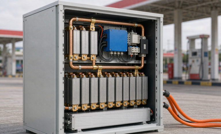
Let me walk through a real class of project: a 250 kW peak, 500 kWh sodium-ion system behind a factory meter, discharging for two hours to shave the evening demand charge. The cells are rated 0.5C continuous, so 500 kWh at 0.5C gives exactly 250 kW, and I select a 250 kW PCS with a 10-minute 110 percent overload allowance for transformer inrush. The pack is built from prismatic sodium-ion cells arranged in strings that present a 600 V to 750 V DC bus to the inverter, comfortably inside the PCS DC input range.
For interconnection I model the point of common coupling and confirm the inverter’s THD stays under 5 percent at full power, set the power factor band to plus or minus 0.95, and enable IEEE 1547 frequency-watt and volt-var modes. Compared with a lithium iron phosphate design of equal energy, the sodium-ion version needs a slightly larger cabinet and yields a few points less round-trip efficiency, but it costs less per kilowatt-hour and needs no cold-weather heating. For a custom battery solution where the customer prioritizes upfront cost and cold resilience over maximum density, sodium-ion is the right call, and the inverter sizing math is identical once you respect the C-rate.
Frequently Asked Questions
What UL 1741 listing does a sodium-ion grid inverter need?
You need a UL 1741 listing with either Supplement B for basic anti-islanding or Supplement A for full grid-support functions, alongside IEC 62109 safety and FCC Part 15 Class A emissions compliance. The listing applies to the power conversion system, not to the cells, so the sodium chemistry does not alter the requirement.
How do I size the inverter for a 2-hour sodium battery?
Divide the pack energy by the discharge duration to get average power, then match the inverter to the cells’ continuous C-rate. A 500 kWh pack at 0.5C delivers 250 kW, so a 250 kW PCS is appropriate, with a short overload margin for inrush currents.
Can sodium-ion pass IEEE 1547 anti-islanding tests?
Yes. Anti-islanding is a function of the inverter’s control firmware, not the battery chemistry. A properly listed sodium-ion PCS detects loss of grid voltage or frequency and ceases to energize the dead grid within the two-second limit required by IEEE 1547.
What THD limit applies to grid-tied battery inverters?
IEEE 1547 caps current total harmonic distortion at 5 percent at the point of common coupling for most interconnections, with tighter limits under some regional grid codes. A well-filtered silicon carbide PCS typically measures 2 to 3 percent.
Does cold weather change sodium-ion inverter sizing?
Not the inverter rating itself. Sodium-ion’s strong low-temperature performance means you can skip the battery cabin heater that a lithium battery pack would need, removing a parasitic load and keeping the PCS operating point stable through winter.
How long does interconnection approval usually take?
For a small behind-the-meter system the utility review often takes four to twelve weeks depending on the queue and whether a formal interconnection agreement is required, so I start the paperwork in parallel with the inverter selection rather than after it.
Further Reading
References