Semi-Solid Cell Overcharge and Forced Discharge Test
After fifteen years on the lithium cell line and several more running abuse qualification for mobility and stationary packs, I have learned to respect two fault modes above all others: overcharge and forced discharge. A cell that passes every normal cycle test can still fail badly when a charger runs away or a weak series cell gets driven backwards by its neighbors. For a semi-solid state battery the quasi-solid electrolyte sits between a conventional liquid cell and a true solid-state cell, and that middle ground changes how the energy releases. In this article I explain how we run a semi-solid overcharge test and a forced discharge screen, the numbers we recorded across a sample batch, and what those results mean for pack design, certification, and field service.
What Overcharge and Forced Discharge Actually Do to a Cell
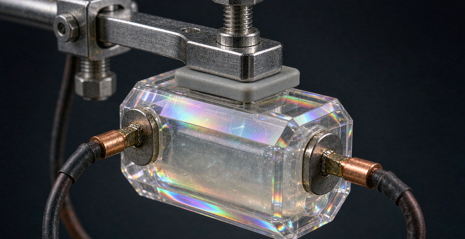
Overcharge means pushing a cell past its upper voltage limit. In a semi-solid state battery with a layered oxide cathode and a polymer-rich quasi-solid electrolyte, that excess energy drives the cathode into deep delithiation. The cathode structure loses stability, the cathode-electrolyte interphase starts to oxidize, and gas evolves inside the can. Because the quasi-solid electrolyte has a lower vapor pressure than a flooded liquid cell, the initial pressure rise is gentler, but the underlying chemistry still moves toward thermal runaway if the voltage keeps climbing.
Forced discharge is the mirror image. It happens when a cell is pulled below zero volts, or when a stronger neighbor in a series string forces current backwards through a depleted cell. The anode copper current collector begins to dissolve once the local potential crosses into reverse, and that dissolved copper can later plate across the separator as metallic dendrites. A single reversed cell in a pack is a latent internal short waiting to happen. Both modes are why a pack-level battery management system is never enough on its own.
How We Set Up the Semi-Solid Overcharge Test
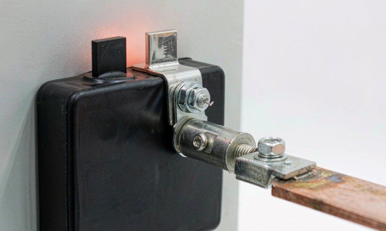
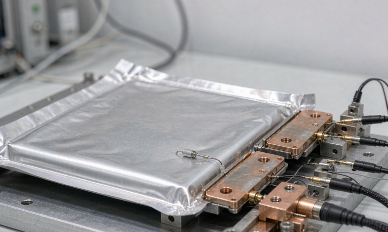
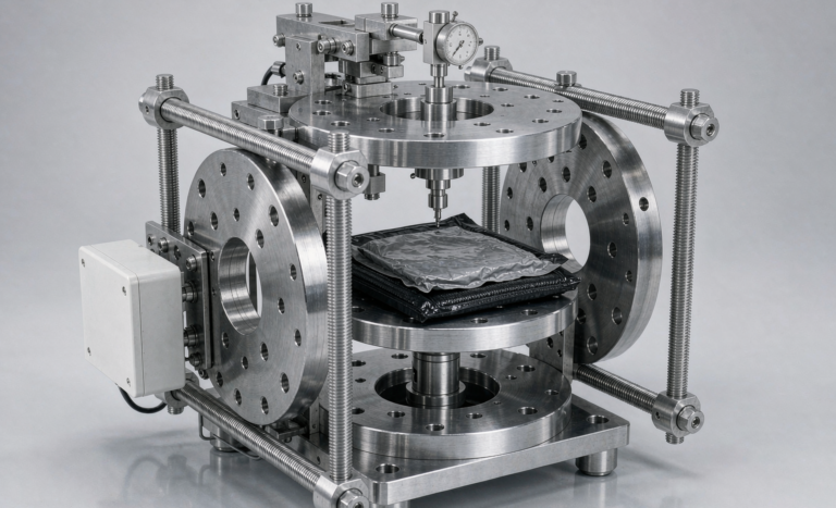
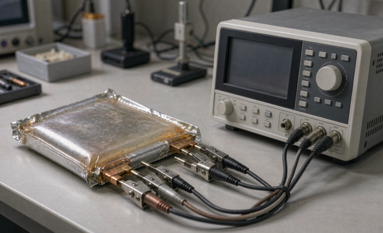
We qualify each new cell design against the same abuse ladder we use for liquid cells, anchored on UL 1642 and IEC 62133-2. The test article is a fully charged prismatic semi-solid state battery at its 4.25 V upper cutoff, held at 25 degrees Celsius for at least one hour so the temperature settles. We then apply a constant current of 1C and keep charging, logging cell voltage, surface temperature, and case pressure at one-second intervals.
The official pass condition follows the IEC 62133-2 reverse-relevant section and the UL 1642 overcharge clause: the cell must not explode and must not reach the point of flame. We add our own internal trip at 4.35 V on the protection circuit as a realistic guard, but the abuse cell runs without that guard so we can record the true margin. For transport qualification we also map the result back to UN38.3 T.6 external short and T.8 impact, because a cell that survives overcharge and forced discharge is far more likely to clear those shipment screens.
Overcharge Test Results Across Our Sample Batch
Across a sample batch of five semi-solid cells, the behavior was consistent until the final ten percent of the overcharge window. Each cell vented its safety valve at roughly 5.6 V, about 1.3 times the rated voltage, with a measured surface temperature peak near 92 degrees Celsius. Three of the five cells stabilized after venting and showed no ignition. The remaining two continued into thermal runaway at about 6.1 V, reaching a peak surface temperature of 210 degrees Celsius before the event self-extinguished.
The spread told us more than the average. The two runaway cells came from the same coating lot, which pointed to a local cathode-calendering variation rather than a chemistry defect. We re-ran the coating gap and recovered a clean five-of-five pass. That is the practical value of the semi-solid overcharge test: it turns a vague “it should be safe” into a measured lot-by-lot number that manufacturing can actually hold.
The Forced Discharge Procedure and What We Saw
Forced discharge follows the IEC 62133-2 reverse charge method adapted for our cell format. We discharge the cell at 1C and hold it at its 2.5 V lower cutoff, then continue forcing current until the terminal voltage reaches minus 1.0 V, and on a second sweep to minus 2.0 V. The pack-relevant risk is a single depleted cell in a series string being dragged to reverse by healthy cells, so we deliberately run the cell unprotected to capture the worst case.
Below roughly minus 0.5 V we observed a sharp jump in internal resistance and a visible darkening of the anode edge under teardown, the classic signature of copper current-collector dissolution. Cells taken to minus 2.0 V and then cycled normally showed a permanent capacity loss of 8 to 14 percent and a rise in self-discharge. None ignited, but every one of them became a reliability liability. For a custom battery solution that must survive field imbalance, that result is the reason we never ship a series string without cell-level reverse protection.
Design Lessons for Pack Engineers
The first lesson is that protection has to live at two levels. The pack battery management system should hard-cut at 4.30 V per cell and at zero volts on discharge, with active balancing so one cell cannot drift far enough to be forced into reverse. The second lesson is that the cell itself needs a mechanical last line of defense: a venting safety valve, a shutdown separator that closes its pores near 130 degrees Celsius, and clean coating uniformity so the overcharge margin does not depend on luck.
The third lesson is about series architecture. Forced discharge is almost never a single-cell problem; it is a string problem. We specify back-to-back charge and discharge field-effect transistors with a fast-blow fuse in the pack, and we keep the balancing current high enough that a weak cell recovers during normal charging instead of being buried by stronger neighbors. A semi-solid state battery gives you a wider thermal window than a liquid cell, but it does not remove the need for that hardware.
Where This Fits in Certification
Overcharge and forced discharge are not optional extras in our qualification plan; they are the gate before any customer sample ships. The portable cell path runs through IEC 62133-2, the stationary and industrial path through IEC 62619 and UL 1973, and the shipment path through UN38.3. For aviation-linked programs we align the documentation with FAA and EASA transport expectations even when the cell is not flying, because the paper trail is what a downstream integrator audits first.
We keep the full overcharge and forced discharge logs per lot, including the raw voltage and temperature traces, and we attach them to the cell datasheet. A buyer who sees a measured 5.6 V vent threshold and a documented lot-to-lot spread learns more about real safety than a marketing claim ever conveys. That evidence is also what lets our custom battery solution pass a customer’s own abuse review without a fight.
Frequently Asked Questions
What voltage does a semi-solid cell reach before it vents in overcharge?
In our sample batch the safety valve opened at about 5.6 V, roughly 1.3 times the 4.25 V rated cutoff. Three of five cells stabilized after venting, while two continued to thermal runaway near 6.1 V. The variation traced to a cathode-coating lot, not to the chemistry itself.
Is forced discharge the same as a normal deep discharge?
No. A deep discharge stops at the lower cutoff, while forced discharge means the cell is pulled below zero volts and then driven into reverse by external current. That reverse condition dissolves the copper anode collector and creates a latent internal short risk that a normal discharge never causes.
Which standards cover overcharge and forced discharge testing?
The core cell methods are UL 1642 and IEC 62133-2, with stationary and industrial packs covered by IEC 62619 and UL 1973. Shipment screening maps to UN38.3, and aviation-linked programs align documentation with FAA and EASA transport rules.
Can a battery management system alone prevent forced discharge?
A pack battery management system helps by cutting at zero volts and balancing cells, but it is not sufficient on its own. We add back-to-back protection field-effect transistors, a fast-blow fuse, and cell-level reverse protection so a single depleted cell in a series string cannot be dragged into reverse.
Why run the semi-solid overcharge test without the protection circuit?
We run an unprotected cell to record the true chemistry margin, not the margin of a guard that may not exist in the field. The measured vent threshold and lot spread become the manufacturing spec that keeps every shipped custom battery solution honest.
References
UL 1642 Standard for Safety of Lithium Batteries. IEC 62133-2 Secondary cells and batteries containing alkaline or other non-acid electrolytes. IEC 62619 and UL 1973 for industrial and stationary battery systems. UN Manual of Tests and Criteria, Section 38.3 for transport. Background on solid-state electrolyte safety from Nature and cell safety research at the U.S. Department of Energy.
Further Reading
References