Home Energy Storage Communication Protocols Explained
When a homeowner asks why their new battery will not charge, nine times out of ten the problem is not the cells. It is the conversation between the battery and the rest of the system. A modern home energy storage system is a small controlled network, and that network speaks in defined languages. Get the protocols wrong and the inverter may refuse to draw from the pack, or the safety contactor may never close. As a senior lithium battery engineer who has commissioned hundreds of residential systems, I treat the communication bus as seriously as the busbars. Here are the three protocols you will actually meet in a home battery, and how they fit together on a real install.
Why Communication Protocols Sit at the Heart of Every Home Battery
A home energy storage battery is only useful when its battery management system, or BMS, can tell the hybrid inverter what the pack can safely do right now. The BMS measures cell voltage, pack current, and temperature many times per second, and computes state of charge and health. The inverter needs that picture to set currents without exceeding the pack’s voltage or temperature window. Without a live link the inverter guesses, and guesswork is what trips warranty claims and safety limits.
The link is also the safety channel. If the BMS detects overvoltage, overtemperature, or an internal fault, it must command the inverter to stop in well under a second over the same bus. So when I specify a residential battery storage system, my first question is not “how many kilowatt hours” but “which protocol does your inverter speak to the battery”.
CAN Bus: The Real-Time Backbone Between BMS and Inverter
Controller Area Network, or CAN bus, is the workhorse for battery-to-inverter communication. Born in vehicles, it suits a battery pack: deterministic, noise tolerant, and no host computer needed to arbitrate who talks. In a home battery we almost always use CAN 2.0B with 29-bit identifiers at 250 kbps, though some brands use 500 kbps. The BMS is one node; the inverter is another.
On this bus the BMS publishes a heartbeat roughly every second: pack voltage to plus or minus 0.1 percent, current to plus or minus 0.5 percent of full scale, state of charge to 0.1 percent, temperatures, and alarm flags. The inverter publishes allowable charge and discharge currents and contactor requests. If the heartbeat stops for three to five seconds it trips to a fault and disconnects. That watchdog is a feature, not a bug: I have seen more than one “dead battery” that was just a loose CAN terminator dropping the heartbeat.
Practically, the battery and inverter must share a protocol dialect, not just the physical bus. A Pylontech-style CAN frame, a Victron frame, and a vendor-specific 29-bit map are not interchangeable even at the same baud rate. I set both ends to the same named profile, confirm the 120 ohm terminators, and watch the heartbeat appear on the inverter screen before closing the DC contactor.
Modbus: The Integration Layer for Monitoring and Energy Management
Where CAN bus is the fast, closed loop between battery and inverter, Modbus is the slower, open layer that lets a logger or cloud gateway read what the system is doing. Most residential setups use Modbus RTU over RS485 at 9600, 19200, or 38400 baud with 8 data bits, no parity, 1 stop bit, or even parity on noise-prone runs. Function code 0x03 reads holding registers; 0x06 or 0x10 writes them.
I treat Modbus as read-mostly telemetry. The gateway polls registers for voltage, current, energy throughput, state of charge, and fault codes, then pushes them to the app; control commands use the same map but sit behind installer credentials. Modbus is polled, not pushed: if the logger polls every two seconds but the BMS updates every second, charts stair-step. That is normal.
Modbus TCP appears when the system bridges to a local network, keeping the same SunSpec-style register map on Ethernet. Either way, the homeowner’s dashboard rides on Modbus while the safety loop rides on CAN bus.
RS485 and RS232: The Physical Layer That Wins in a Home
Protocols need a wire, and the wire matters. RS485 is a differential pair: it drives the line with a plus or minus 1.5 to 5 volt swing between two wires, which rejects the common-mode noise you get next to an inverter. It supports 32 unit loads on one daisy-chained bus, runs past 1000 meters at lower baud, and tolerates a common-mode range near minus 7 to plus 12 volts. RS232 is single-ended and noise sensitive, so it survives mostly as a laptop commissioning port.
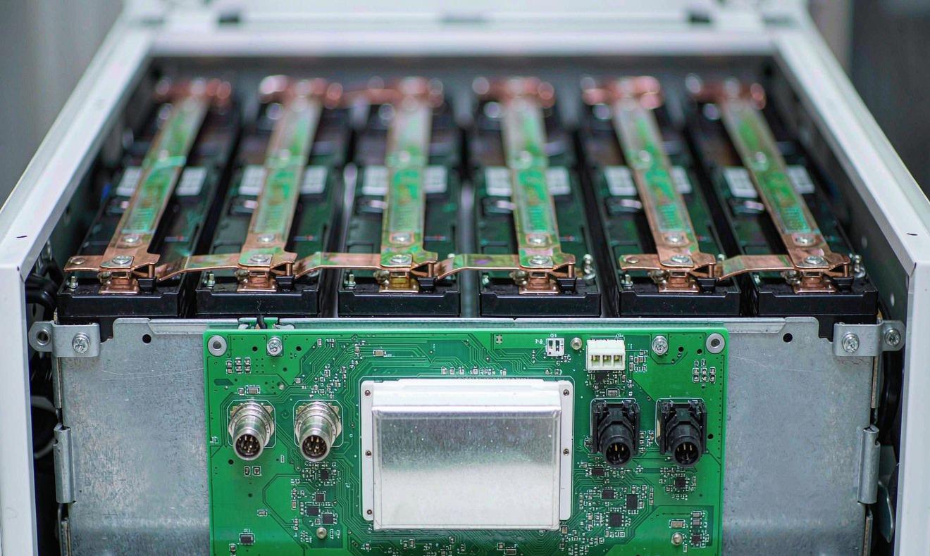
In a home battery cabinet I run RS485 between the BMS, the inverter comms port, and the gateway, terminated at both ends with 120 ohm resistors, with the shield tied to earth at one point only to avoid ground loops. The termination is not optional: without it, reflections corrupt bytes above a few thousand baud and produce cyclic redundancy check errors that look like random dropouts. I have fixed more “flaky batteries” with a missing terminator than by touching a single cell.
How the Protocols Fit Together in a Real System
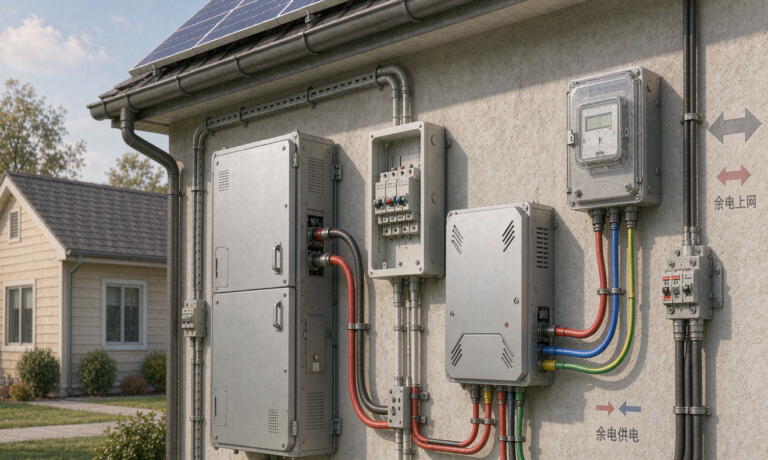
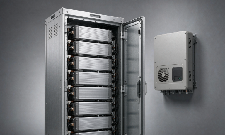
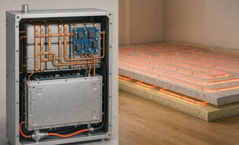
Picture a typical install. Lithium cells sit in modules wired to a BMS, which talks CAN bus to the hybrid inverter for the real-time charge loop and safety heartbeat. A separate RS485 pair carries Modbus to a data logger, which converts it to Modbus TCP or Wi-Fi for the cloud. The homeowner’s phone never touches CAN bus directly; it reads the logger’s translation.
The separation is deliberate. The safety-critical loop stays on a small, fast, isolated bus with no internet exposure, while the convenience layer sits on a slower bus that can be bridged to the network. Mixing them is how a router reboot can silence a safety heartbeat.
Commissioning and Troubleshooting in the Field
Most communication faults are boring and repeatable. The first is a baud or parity mismatch: the inverter expects 19200 8N1 and the battery ships at 9600 8E1, so registers return garbage. The second is a duplicate node ID, where two devices answer one address. The third is a missing 120 ohm terminator, which shows up as intermittent cyclic redundancy check errors that worsen when the inverter fan spins up.
My field routine is fixed. Confirm the named CAN profile on both ends and verify the heartbeat on the inverter screen, then walk the Modbus side: set baud and parity, assign unique node IDs, fit the terminators, and read register 0x0000 to prove the link. If the heartbeat vanishes, measure the terminator resistance; it should read about 60 ohms with both ends fitted, because two 120 ohm resistors sit in parallel. Near 120 ohms means one terminator is missing; near open means the pair is broken.
Isolation and Safety: Keeping the Bus Away From High Voltage
The communication bus lives next to a pack that can deliver hundreds of amps, so isolation is not a detail. I specify optocouplers or isolated transceivers rated to at least 2.5 kilovolts RMS between logic and pack side, and keep the CAN and RS485 transceivers on the isolated plane. Comms wiring is treated as SELV, separated from the high-voltage dc bus by reinforced insulation, and routed in its own conduit so a chafed AC line never shorts into the data pair.
A home battery on the network is now a small internet device, so I apply industrial discipline: change default credentials, keep gateway firmware current, and keep the safety CAN loop off any routable network. Standards such as IEC 62443 describe the layered approach, while the product still answers to UN38.3 for transport, IEC 62133 and IEC 62619 for cell and pack safety, and IEEE 1547 with UL 1741 for grid interconnection. EMC immunity and emission follow IEC 61000-6-2 and 61000-6-4 so the bus stays quiet next to inverter switching noise.
Choosing the Right Stack for Your Home
If you are specifying a home battery backup, the rule is simple. Buy a battery and inverter that publish a common CAN dialect, not just “CAN compatible”, because compatible at the physical layer is not compatible at the message layer. Use RS485 for the Modbus telemetry run, fit both terminators, and keep node IDs unique. Let the cloud dashboard ride on the Modbus side, and keep the safety loop isolated and offline.
A residential battery storage system wired this way commissions in an afternoon and stays quiet for years. One that ignores the protocol match becomes a support ticket the first time a firmware update changes a register map.
Frequently Asked Questions
What is the difference between CAN bus and Modbus in a home battery?
CAN bus is the fast, real-time link between the battery management system and the inverter that carries the safety heartbeat and charge limits, usually at 250 kbps. Modbus is the slower, polled integration layer that a logger or gateway uses to read telemetry and push it to an app, typically over RS485 at 9600 to 38400 baud. The first keeps the system safe; the second keeps the homeowner informed.
Can I mix batteries and inverters from different brands?
Only if both publish the same named communication protocol, not merely the same physical bus. A battery and inverter may both have a CAN port yet speak different message maps, in which case the inverter cannot read state of charge or limits and will fault. Always confirm a documented compatibility profile before mixing brands.
Why does my battery show a communication error after a firmware update?
A firmware update can change the Modbus register map or the CAN dialect version. If the inverter or gateway still expects the old map, registers return errors or the heartbeat stops, and the inverter trips on its watchdog. Re-match the protocol profile on both ends after the update, or roll back the firmware, to restore the link.
What baud rate and node ID should I use for RS485 Modbus?
Use the baud and parity the battery and logger document specify, commonly 9600 or 19200 baud with 8 data bits and no parity, and assign a unique node ID to every device on the daisy chain. Duplicate IDs cause address collisions and corrupted reads, so I label each ID at commissioning.
Is RS485 safe to run next to AC power cables?
RS485 is differential and noise-tolerant, so it can run in the same conduit as AC if separated by a grounded partition and kept away from parallel runs longer than a meter, but I prefer a dedicated low-voltage conduit. Fit 120 ohm terminators at both ends, tie the shield to earth at one point only, and treat the pair as SELV isolated from the high-voltage dc bus.
Do home energy storage systems need the internet to communicate?
No. The safety-critical CAN loop between the battery and inverter is local and works with no internet. The internet is only needed for the cloud dashboard and remote alerts, which ride on the separate Modbus side. A router outage will pause your app, not your backup power.
How can I tell if the BMS is actually talking to the inverter?
Check the inverter’s commissioning screen for a live state of charge and a heartbeat at about one per second. On the wiring, measure about 60 ohms across the CAN pair with both terminators fitted. If the heartbeat is absent or the resistance reads near 120 ohms, a terminator or connection is missing and the inverter will trip.
Further Reading
References