Lithium Battery Thermal Interface Material Selection Guide
Why Thermal Interface Materials Decide Pack Reliability
When I audit a failed lithium battery pack, the root cause is rarely the cell itself. It is the path the heat has to travel to escape. A lithium battery pack generates heat during charge and discharge, and that heat has to reach a cold plate before the cells drift out of their safe window. The thermal interface material is the bridge between the cell and the cooler. If that bridge is thick, soft, or full of trapped air, the cells run hot, the balancing circuit works harder, and cycle life drops faster than the data sheet promised.
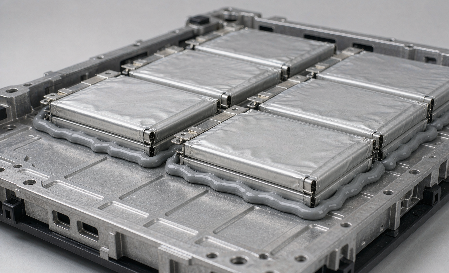
In my fifteen years building custom battery solutions for medical and industrial customers, I have learned to treat the gap filler as a structural part, not an afterthought. Buyers ask about capacity and cycle life. They almost never ask about thermal resistance. Yet the thermal interface material is what determines whether a pack quietly does its job for eight years or shows up as a warranty return in month fourteen. The cheapest gram of material in the pack is often the one that protects the most expensive gram, which is the cell.
I have seen well engineered prismatic designs lose half their usable life simply because a dispensing step was skipped on one shift. The cells were identical. The cooling loop was identical. The only difference was the bond line, and the bond line is the thermal interface material. That is why I spec it first and defend it during production, not after a field failure.
How Heat Moves From the Cell to the Cold Plate
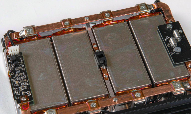
Heat leaving a cell crosses four steps in series. First it moves from the cell core through the can or pouch wall. Then it crosses the thermal interface material. Then it enters the cold plate. Finally the coolant carries it away. Each step is a thermal resistor, and in most packs the largest resistor is the interface layer, not the cell and not the plate.
The numbers are not abstract, and they are worth memorizing. A bare aluminium cell wall of one millimeter adds roughly 0.0009 square meter kelvin per watt. A one millimeter air gap in the same joint adds about 0.25 square meter kelvin per watt, which is roughly two hundred times worse. A dispensed silicone gap filler rated at 2 watts per meter kelvin, used in that same one millimeter bond line, drops the resistance to about 0.0005 square meter kelvin per watt. The lesson is simple. Air is the enemy, and the thermal interface material is what keeps air out of the joint.
I spec the interface before I size the cooling plate. Starting from the cold plate and hoping the cells stay cool is a mistake I have corrected on too many legacy designs. When the interface is right, a modest cooling loop suddenly has margin it never had, and that margin is what survives a hot summer or a sustained high discharge.
Silicone, Polyurethane, and Phase Change Gap Fillers
There is no single best thermal interface material. There are three families I reach for, and each trades one property for another. Silicone dispensable gels are my default for a lithium battery pack because they conform to uneven surfaces and survive vibration. They cure in place, fill voids, and stay flexible across a wide temperature range, which matters when the pack sees both cold storage and full load.
Polyurethane gap fillers are tougher and resist pump out under repeated thermal cycling, but they are less forgiving on rework and can stress a thin pouch wall if over compressed. Phase change materials stay solid at room temperature and flow once the pack warms, which keeps the line clean during assembly and gives very low contact resistance once running. The cost is process control, because a phase change material must be compressed to the correct bond line before it melts, or it will not perform.
For any design destined for transport or enclosed spaces, I also check flammability. A gap filler that is not rated UL 94 V-0 has no place in a lithium battery pack that has to pass UN38.3 or IEC 62133. I have rejected otherwise excellent materials on that single test, because a pack that cannot show its fire safety rating is a liability the moment it ships.
Choosing Bond Line Thickness and Compression
The bond line is the thickness of thermal interface material under compression. Thinner is better for thermal resistance, but only if the surfaces are flat. Real cell cans and cold plates are not perfectly flat, so a bond line below about 0.2 millimeter will leave voids that behave like air gaps. I usually target 0.3 to 0.8 millimeter for dispensed materials and verify the actual compressed value on the line.
Compression matters as much as thickness. Too much force bows the cells or the plate, and too little leaves the interface loose enough to pump out. For a prismatic lithium battery pack I design for 20 to 50 percent compression of the dispensed layer and confirm it with a fixture, not by eye. The goal is a repeatable bond line, because a pack that varies from unit to unit will fail in the field in ways the lab never reproduced.
Surface flatness decides the floor on thickness. If the cold plate is milled flat and the cell cans are consistent, I can run a thinner bond line and gain thermal margin. If either surface is rough, I open the bond line slightly and accept the small resistance penalty rather than risk voids. Engineering is the art of choosing the safe side of that trade.
Application Method and Process Control
How the thermal interface material reaches the pack decides whether the spec survives contact with the factory floor. Automated dispensing gives a consistent bead and lets me log the volume placed on every unit, which is exactly the data I want when a customer asks about traceability. Pre cut pads are faster for low volume custom battery solutions, but they trap air at the edges if the operator is not trained and the placement is not fixtured.
Voids are the silent killer. A small bubble in the bond line can double the local thermal resistance and create a hot spot that ages one cell faster than its neighbors. I inspect critical packs with X ray or infrared imaging during qualification, and I keep a written disposition rule for void area so the line knows when to stop and rework rather than ship. A pack with one hot cell is a pack with a clock running.
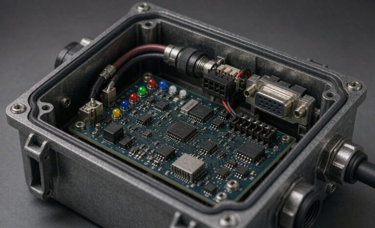
I also watch outgassing on cured materials. In a sealed enclosure, volatiles from a poor gap filler can condense on connectors or fog an optical sensor in the same box. This is a detail that never appears in a marketing brochure but always appears in a returned unit, so I qualify the material in the actual enclosure, not in open air.
Qualification for Production Custom Battery Solutions
A gap filler that looks right on the bench can drift in production, so I qualify the joint, not just the material data sheet. The test plan includes thermal cycling from minus 20 to 60 degrees Celsius, damp heat at 85 percent relative humidity, and a measurement of thermal impedance before and after the cycle to catch pump out or cure shrinkage. If the impedance moves, the bond line moved, and the design is not ready.
For packs that ship, I align the design to UL 1973 and IEC 62619 for stationary and industrial use, and I keep the UN38.3 test summary current and accessible. A lithium battery pack that cannot show its thermal qualification is a liability, not a product. In my experience the customers who ask about the thermal interface material early are the ones who never call me about field failures, because the question itself means they are thinking about the whole pack, not just the cell.
The last step is a production sample audit. I pull units from the first real run, measure the bond line, and confirm the thermal resistance matches the qualification article. Only then do I release the custom battery solution to volume, because the interface is the one part that is easy to skip when a line is under pressure to ship.
Frequently Asked Questions
What thermal conductivity do I need for a lithium battery pack?
For most industrial packs a thermal interface material rated 2 to 5 watts per meter kelvin is enough when the bond line is controlled. High discharge cells or tight enclosures may need 6 watts per meter kelvin or a directly bonded cold plate. Start from your heat load and your allowable temperature rise, then work backward to the conductivity rather than picking a number from a catalog.
How thick should the thermal interface material be?
Target a compressed bond line of 0.3 to 0.8 millimeter for dispensed gap fillers. Thinner risks voids on uneven surfaces, and thicker adds resistance. The flatness of the cell and the plate decides the practical floor, so measure both before you commit to a thickness.
Can I reuse gap filler during pack repair?
No. Once a dispensed thermal interface material is compressed and cured it should be removed and replaced. Reusing it leaves voids and changes the bond line. For repairable packs I prefer pads or phase change materials that can be lifted and reseated cleanly without contaminating the cell surface.
Does thermal interface material affect battery weight?
Only slightly. A typical lithium battery pack uses a few grams of gap filler per cell, which is a fraction of a percent of total mass. The thermal benefit far outweighs the weight, and a well managed interface can even let you shrink the cooling plate and save more mass than the filler adds.
How do I test thermal interface performance in production?
Qualify with thermal impedance measurement before and after cycling, and use infrared or X ray to check voids on a sample basis. For high volume custom battery solutions I log the dispensed volume per unit so any drift in bond line shows up in the data before it reaches the field, which turns a hidden failure mode into a visible trend.
Further Reading
References