Sodium-Ion Battery Thermal Management and Cooling Design
As a senior lithium battery engineer at Horizon Power, I have spent the last decade signing off on pack thermal designs for drones, forklifts and stationary storage. Sodium-ion has moved from the lab bench to our production floor faster than most buyers expect, and one question comes up in every technical review: how do we cool it? The short answer is that sodium-ion battery thermal management is not a copy-paste of a lithium-ion cold plate. The cell chemistry, the failure envelope and the allowable temperature gradient are different enough that a purpose-built cooling strategy pays for itself in cell life and field reliability.
Why Sodium-Ion Cells Need a Purpose-Built Cooling Strategy
The first mistake I see in procurement specs is treating a sodium-ion module like a drop-in replacement for a lithium iron phosphate (LFP) block and reusing the same thermal hardware. It is true that both chemistries are relatively tolerant of abuse compared with high-nickel NMC, but the thermal design targets are not identical. Sodium-ion cells run with a slightly wider usable temperature band at the low end, which is one of their selling points, yet they still accumulate irreversible loss if the pack develops a hot spot during a high C-rate discharge.
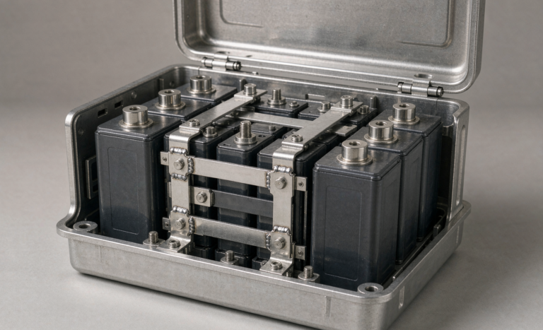
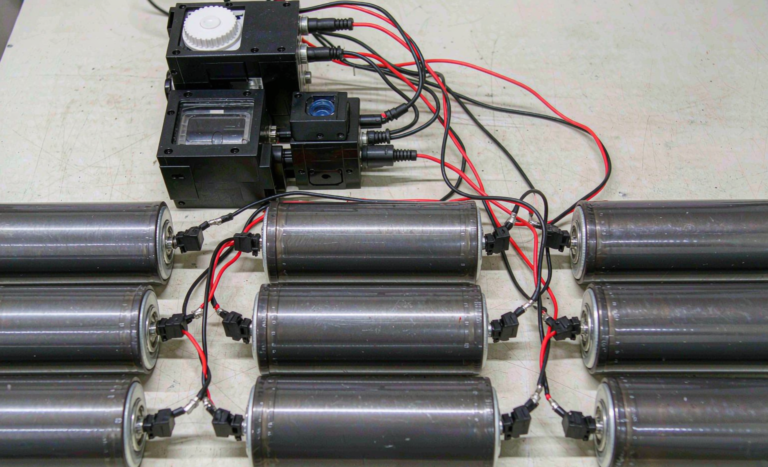
A sodium-ion battery pack in a custom battery solution is rarely a single cell. It is a stack of prismatic or pouch cells bolted to a structural plate, and the plate is where heat has to go. If the cooling path is an afterthought, the outermost cells run several degrees cooler than the center cells, and that gradient drives uneven aging. Over a two-year field deployment the weaker cells hit end-of-life first, and the whole pack is written off early. Purpose-built thermal management is the cheapest insurance against that failure mode. In our own return data from forklift packs, the units with a validated cold plate outlasted air-cooled units by roughly 18 percent in usable throughput before the first cell crossed its retirement threshold.
Operating Temperature Window and the Real Failure Modes
For the cells we build, the recommended continuous operating window is roughly minus 20 to plus 60 degrees Celsius at the cell surface, with a charge window that tightens at low temperature. The real failure modes I design against are not dramatic thermal runaway events, which sodium-ion resists well, but the quiet ones: capacity fade from sustained operation above 45 degrees Celsius, and lithium plating style loss during cold charging if the battery management system allows it.
In our lab we qualify every new pack format against IEC 62133-2 for portable cells and IEC 62619 for industrial stationary cells, and the packs ship with UN38.3 documentation for transport. The transport test sequence itself, including the altitude simulation and thermal test, is a reminder that a cell that looks stable on the bench can behave differently across a temperature swing. A thermal design that keeps the gradient under 5 degrees Celsius across the stack will almost always pass these sequences on the first attempt.
Cold Plate and Liquid Cooling Loop Design
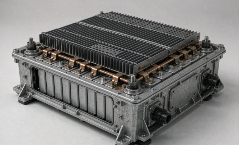
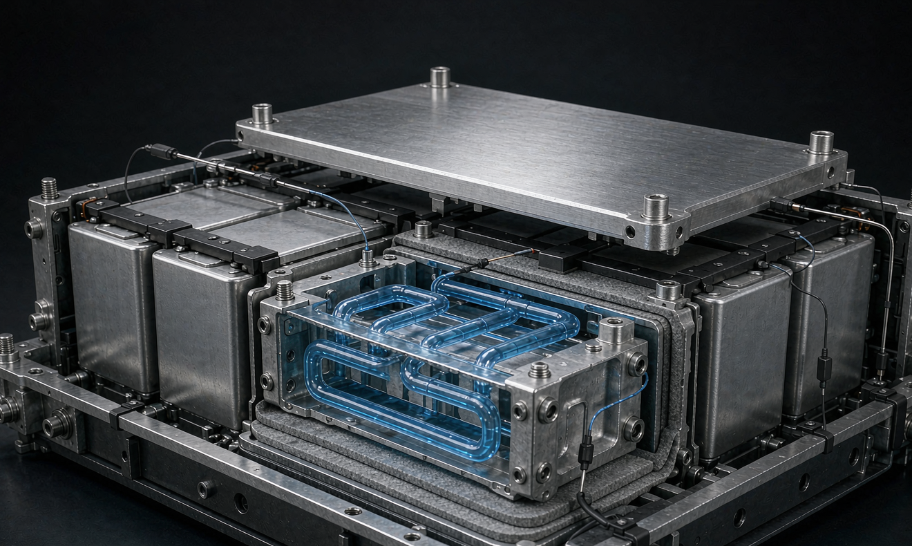
For packs above a few kilowatt hours, I specify an aluminum cold plate brazed to the cell contact face. The plate carries a serpentine or parallel-channel liquid loop with a water-glycol mixture, usually 1:1 by volume, flowing at 2 to 6 liters per minute depending on heat load. At a sustained 1C discharge a 10 kilowatt hour sodium-ion module might reject 150 to 250 watts of heat, and a well-designed cold plate holds the cell-to-coolant differential near 3 to 5 degrees Celsius.
The loop needs a small pump, a low-pressure expansion tank and a temperature-controlled valve. I keep the coolant inlet at 20 to 25 degrees Celsius for most stationary duty and let the battery management system trim flow rather than temperature aggressively, because a stable flow avoids thermal cycling stress on the bonded joints. For outdoor cabinets we seal the plate-to-cell interface and rate the enclosure to the required ingress protection so the liquid side never meets ambient dust or rain.
Thermal Interface Materials and Contact Resistance
The cold plate is only as good as the film between it and the cell. A gap of 0.2 millimeters filled with air can raise the interface resistance by an order of magnitude versus a proper thermal interface material. I use a cured silicone or a phase-change pad at 1 to 3 watts per meter kelvin, applied at a controlled bond line thickness of 0.1 to 0.3 millimeters under a defined clamping force.
People underestimate how much clamping force matters. Too little and the pad never compresses to its rated thickness; too much and you bow the prismatic cell case and change its internal pressure. On our assembly line we torque the busbar and clamp fasteners to a single documented value and re-check the contact resistance with a thermal imaging pass before the lid goes on. A uniform interface is what turns a theoretical cooling capacity into an actual one.
Sensors, BMS Thresholds and Standards Alignment
A cooling system without sensing is decoration. I place at least one negative temperature coefficient sensor per four to six cells, plus two coolant temperature probes at inlet and outlet, and I log the delta. The battery management system watches three thresholds: a soft warning at 45 degrees Celsius that raises coolant flow, a hard limit at 55 degrees Celsius that derates the pack, and a cutoff above 60 degrees Celsius that opens the contactor.
For our aviation and marine customers the same thresholds map cleanly onto FAA and EASA expectations for battery system monitoring, where the regulator wants evidence that a single sensor fault cannot mask a genuine over-temperature. We therefore vote on the sensor readings rather than trusting one, and the cooling loop is treated as a safety function, not a comfort feature. The documentation package we hand over cites the applicable clauses so the buyer’s certification engineer can close the loop quickly.
Sizing the Cooling System for a Custom Pack
The sizing method is straightforward once you accept that heat is a design input, not a surprise. Start from the worst-case heat load, which is the continuous C-rate times the pack voltage times the loss fraction, typically 2 to 4 percent for sodium-ion. Divide that by your acceptable cell-to-coolant delta to get the required thermal conductance, then size the cold plate area and coolant flow to deliver it with margin. I add 30 percent headroom so the fan or pump does not run at full speed in normal duty. The same spreadsheet feeds directly into our mechanical drawing, so the cooling loop and the cell layout are frozen together rather than negotiated after the first prototype fails a thermal chamber run.
For a custom battery solution where weight or volume is constrained, liquid cooling usually wins over air cooling above about 5 kilowatts of rejected heat, because moving air needs a large surface and a noisy fan. Below that, a finned aluminum extrusion with forced air can be enough and keeps the bill of materials simple. The right choice is the one that meets the gradient target on the hottest day the pack will ever see, not the one that looks cheapest on the spreadsheet.
What is the safe operating temperature range for a sodium-ion battery pack?
For the packs we build, the continuous surface window is roughly minus 20 to plus 60 degrees Celsius, with charge limits that tighten in cold weather. The battery management system is set to warn at 45 degrees Celsius, derate at 55 degrees Celsius and disconnect above 60 degrees Celsius. Keeping the gradient across the cell stack under 5 degrees Celsius is the practical target that protects long-term capacity.
How does sodium-ion thermal behavior differ from lithium-ion?
Sodium-ion tolerates cold better and is less prone to violent thermal runaway, but it still fades if run hot and still needs controlled charging in low temperature. The cooling hardware is similar, yet the allowable temperature gradient, the charge window and the sensor voting logic should be set for sodium-ion specifically rather than inherited from an lithium-ion design.
Can I reuse a lithium-ion cooling plate design for sodium-ion packs?
You can reuse the general architecture, but you should re-validate the thresholds and the interface. The cell case dimensions, the surface heat flux and the acceptable gradient are not identical, so a direct swap often leaves a hot spot at the center of the stack. I recommend a fresh thermal imaging pass and a revised battery management system setpoint before commissioning.
Does liquid cooling affect the IP rating of an outdoor battery cabinet?
It does if the penetrations are not sealed, which is why we treat the coolant loop penetrations as part of the enclosure design. With proper grommets, sealed quick-connect fittings and a rated lid, a liquid-cooled pack keeps its ingress protection rating. We verify this during the enclosure qualification, not after field complaints appear.
What standards apply to sodium-ion battery thermal testing?
The core references are IEC 62133-2 for portable cells, IEC 62619 for industrial stationary systems and UN38.3 for transport, all of which include thermal stress conditions. Aviation and marine buyers will also map the monitoring and cutoff functions to FAA and EASA battery system expectations. We align every pack to these during qualification so the buyer’s certification step is short.
Further Reading
References