Battery Solution for Wearable Health Monitors: An Engineer’s Field Guide
I am Karl Huang, a senior lithium battery engineer. Over eleven years I have designed cells and packs for drones, industrial robots and, increasingly, devices worn against human skin around the clock. Wearable health monitors are the hardest small-format job I take on. A drone battery gets abused for twenty minutes and then rests in a padded case. A continuous glucose monitor, a Holter ECG patch or a fall-detection pendant must run seven to fourteen days, survive sweat and shower steam, tolerate being slept on, and never get warm enough for a patient to notice.
This guide covers chemistry selection, real energy-budget numbers, certification under IEC 62133-2 and UN 38.3, mechanical and ingress design, and the field failures that taught me the most. If you are specifying a battery solution for a wearable health monitor, this is the engineering reality rather than the datasheet fantasy.
Why a Wearable Health Monitor Is Not Just a Small Consumer Device
The first mistake teams make is treating a medical wearable as a shrunken smartwatch. A smartwatch is charged nightly by a user who tolerates a dead device. A patient-worn monitor is applied by a clinician, sealed, and expected to log continuously until the study ends, with no charging opportunity. If the pack dies on day nine of a fourteen-day arrhythmia study, the clinical data is incomplete and the study may need repeating.
That requirement cascades through every decision. It pushes you toward primary cells or very low self-discharge secondary chemistries, kills any topology with meaningful quiescent drain, and means your capacity margin cannot be the usual ten percent consumer teams get away with. On medical projects I budget at least twenty-five percent headroom at end-of-life, at the coldest specified operating temperature.
The second difference is thermal. A drone battery can sit at 45 degrees Celsius during a hard climb and nobody complains. A device adhered to the sternum must stay below roughly 41 degrees Celsius at the skin interface to satisfy the applied-part surface temperature limits in IEC 60601-1. That ceiling is brutally low, and it makes your discharge profile, DC-DC efficiency and enclosure thermal path part of the battery design rather than separate problems.
Choosing the Right Chemistry for a Wearable Battery Solution
I evaluate four options on nearly every wearable program, and the answer genuinely changes with the use case.
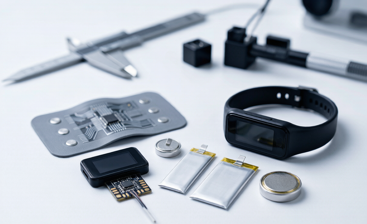
Lithium polymer pouch cells remain the workhorse for rechargeable wearables, at 200 to 260 Wh/kg in the thin formats used in wristbands. A 3.7 V pouch at 5 x 20 x 30 mm gives roughly 150 to 200 mAh, enough for a wrist-worn optical heart-rate monitor on a three to five day recharge interval. The catch is cycle life under the shallow, warm conditions wearables actually see: expect 300 to 500 cycles to 80 percent capacity, not the 1000 the datasheet promises.
Lithium manganese dioxide coin cells are my choice for disposable patches. A CR2032 delivers about 225 mAh at 3.0 V with self-discharge under one percent per year, and for a seven-day ECG patch averaging 200 microamps, one or two coin cells is often the entire answer. The caveat is pulse capability: internal resistance climbs steeply below 0 degrees Celsius and with depth of discharge, so a 15 mA radio burst needs a 100 to 470 microfarad buffer capacitor or you will see brownout resets at 70 percent state of charge.
Lithium thionyl chloride cells top the primary category at 500 to 700 Wh/kg with a flat 3.6 V curve, which suits remote patient monitors serviced in years rather than weeks. The tradeoff is passivation: after long storage the first current pulse can sag badly, so plan a depassivation strategy or a hybrid layer capacitor in parallel.
Semi-solid and thin-film solid-state cells are finally practical in the smallest formats. I have qualified thin-film cells in the 0.5 to 2 mAh range for in-ear biosensor concepts. Their advantage is not energy density but the absence of a liquid electrolyte, which removes leakage and flammability failure modes entirely. Cost is still high, but I now include a semi-solid option in every wearable feasibility study I write.
Building an Honest Energy Budget
Most wearable battery failures I have investigated trace back to an energy budget that was optimistic in three specific places.
First, engineers use typical current draw instead of worst-case. A Bluetooth Low Energy radio does not always connect on the first attempt, and in a noisy hospital ward retry rates of fifteen to thirty percent are normal, each retry being a full transmit burst. I multiply calculated radio energy by 1.3 on any clinical device.
Second, teams ignore temperature derating. A lithium polymer cell rated 200 mAh at 25 degrees Celsius delivers roughly 170 mAh at 0 degrees and around 140 mAh at minus 10 degrees. If your specification claims operation from minus 10 to plus 45 degrees Celsius, your capacity math must use the minus 10 number.
Third, calendar aging gets forgotten. A cell stored at 40 percent state of charge and 25 degrees Celsius loses roughly two to four percent capacity per year, and devices sit in distribution warehouses. With a two-year shelf life, subtract eight percent before you start.
Here is the arithmetic I run for a seven-day disposable ECG patch. Sensing 180 microamps, radio 45 microamps after the retry multiplier, quiescent leakage 12 microamps, totalling 237 microamps. Over 168 hours that is 39.8 mAh; with the twenty-five percent margin I need 50 mAh usable. A CR2032 derated to roughly 140 mAh usable above the 2.5 V cutoff at the coldest specified temperature clears that comfortably. That is a design you can defend in a review.
Safety, Certification and the Standards That Actually Bite
Every cell that leaves my factory has been through UN 38.3, and the term gets used loosely, so to be specific: T.1 altitude simulation at 11.6 kPa, T.2 thermal cycling between minus 40 and plus 75 degrees Celsius, T.3 vibration from 7 to 200 Hz, T.4 shock at 150 g for 6 milliseconds, T.5 external short circuit at 55 degrees Celsius, T.6 impact or crush, T.7 overcharge and T.8 forced discharge. For a wearable pack you run the battery-level sequence plus cell-level T.6 and T.8 on the supplied cells.
IEC 62133-2:2017 is the market access standard for secondary lithium cells in portable applications, and it is where wearable designs most often stumble. The forced internal short circuit test and the mechanical tests on pouch tabs catch weak welds. I have seen two programs fail tab pull strength because a contract manufacturer changed ultrasonic welding parameters without notification. Specify a minimum tab pull strength in the purchase agreement, measure it on incoming inspection, and control welder settings as a critical process parameter.
On the medical layer, IEC 60601-1 clause 11.1 governs applied-part surface temperature, IEC 60601-1-11 adds home healthcare requirements including drop testing, and IEC 60601-1-2 electromagnetic compatibility can force a change to your DC-DC switching frequency, which changes efficiency, which changes your energy budget. Run the EMC pre-scan early. For air transport, IATA PI 970 covers lithium metal in equipment and PI 967 lithium ion in equipment; every wearable sits far under the 20 Wh per cell threshold, so the real task is keeping your UN 38.3 test summary current for the exact cell revision you ship.
Mechanical Design, Ingress Protection and Skin Contact
A wearable battery is a mechanical component before it is an electrical one. The pack will be bent, compressed and soaked.
Pouch cells do not tolerate repeated flexing. If your wristband curves, do not curve the cell: design a rigid pocket and let the strap flex around it, or split into two smaller flat cells at rigid zones. A cyclically flexed pouch eventually delaminates its separator locally, producing an internal soft short that surfaces as accelerated self-discharge weeks later, which is exactly the failure a two-week qualification test misses.
Compression is the second hazard. A patient sleeping on a chest patch applies real force, so I test to a static load of 500 newtons over the pack footprint. Any permanent thickness increase above five percent means gas generation has begun and the design is not ready.
For ingress, IEC 60529 IP67 is the practical target for anything worn in the shower, IP68 with a stated depth for swim-capable devices. Sweat is more aggressive than fresh water because chloride ions drive galvanic corrosion at exposed nickel tabs and dissimilar metal joints. I conformal coat the entire protection circuit module and encapsulate every tab joint. One early program lost a batch to sweat corrosion through a pinhole in the coating, which taught me to specify coating thickness and inspect under UV rather than trust the process.
Thermal path deserves a last word. The cell is often the largest thermal mass in the device and it will conduct heat to skin. I place it on the outward-facing side and add a thin insulating layer, typically 0.3 mm of aerogel-loaded film, on the skin side. Model it, then measure it with a thermal camera on a warm human volunteer, not on a bench at room temperature.
Protection Circuits and Charging for Micro-Format Packs
Every rechargeable wearable pack I ship carries a protection circuit module sized for the cell, not copied from a larger design. For a standard pouch I use overcharge cutoff at 4.28 V with a 1 second delay, over-discharge cutoff at 2.50 V, and an overcurrent trip at roughly three times the maximum application load. A frequent error is setting that trip from the cell datasheet maximum: if the device never draws more than 50 mA, a 3 A trip protects nothing.
Quiescent current is the other specification I refuse to compromise on. Many general-purpose protection ICs draw 3 to 5 microamps; stack that with a fuel gauge and a regulator and you have quietly given away eight percent of a seven-day budget. I now specify sub-microamp protection ICs on any device with a service interval over five days.
Charging is either pogo pins or inductive coupling. Pins are cheap and efficient but corrode and can short across a metal watchband, so add series protection and contact detection that only energizes on a valid dock. Inductive charging removes the ingress problem, which is why I recommend it for IP68 devices, but at 50 to 70 percent efficiency it dumps heat into a small enclosure: charge at 0.3 C or lower with thermal foldback above 40 degrees Celsius pack temperature. And do not charge to a full 4.35 V nightly. Where the daily requirement sits comfortably below capacity, I cap at 4.10 V, which roughly doubles cycle life for about fifteen percent capacity. That is free longevity.
What Field Failures Taught Me
Three years ago I was called to a hospital in Shenzhen where remote cardiac monitors were failing after four to six days instead of fourteen. The clinical team suspected the cells. I took a crate back to the lab and put twelve on a cycler. The cells were fine, within four percent of nominal capacity with normal internal resistance.
The problem was firmware. A connection retry loop had no backoff: when the device lost the gateway link it retried every 200 milliseconds indefinitely. In wards with poor coverage, devices burned their entire energy budget on radio retries. The battery solution was correctly specified; the system was not. Exponential backoff capped at 60 seconds took field runtime to thirteen and a half days.
I tell that story in every design review because the cell is rarely the weakest link. When a client asks me for a custom battery solution for a wearable health monitor, my first request is not a mechanical drawing. It is the firmware power state diagram and a measured current trace from a real prototype, captured on a source measure unit with microamp resolution over at least twenty-four hours. Everything else follows from that trace. The second lesson is incoming inspection: small cells are cheap enough that teams skip receiving tests. I require 100 percent open circuit voltage and internal resistance screening on medical builds, and on one build that caught a sub-lot with a 40 percent resistance excursion which would have passed functional test and failed in month four.
Frequently Asked Questions
What battery capacity does a wearable health monitor actually need?
Build the budget from measured current, not estimates. A continuously sensing patch with periodic Bluetooth Low Energy transmission typically averages 150 to 400 microamps. Multiply by runtime in hours, add a 1.3 factor on the radio for retries, then add twenty-five percent for end-of-life and cold derating. Most seven-day patches land between 40 and 90 mAh usable, multi-day wrist devices between 120 and 300 mAh.
Should I use a rechargeable or a primary cell in a medical wearable?
If the device is disposable and the wear period is under fourteen days, a primary lithium coin cell is almost always cheaper, safer and simpler, and it removes charging hardware, charge safety circuitry and the associated certification burden. If the device is reusable across patients or has a service life measured in months, a rechargeable lithium polymer pack is the right answer despite the added complexity. The break-even in my experience sits around three to four use cycles.
How do I keep the battery from making the device feel warm against skin?
Target under 41 degrees Celsius at the skin interface per the applied-part limits in IEC 60601-1, and get there by minimizing average power rather than adding heat sinking, because a wearable has nowhere to sink heat to. Improve DC-DC efficiency, reduce radio duty cycle, place the cell on the outward face, and insulate the skin side. Verify on a human wearer with a thermal camera, because bench measurements at room temperature underestimate skin-side temperature.
What certifications does a wearable battery pack need?
At minimum, UN 38.3 for transport covering all eight subtests, and IEC 62133-2 for secondary lithium cells and batteries in portable applications. For medical devices add IEC 60601-1 for electrical safety and surface temperature, IEC 60601-1-2 for electromagnetic compatibility, and IEC 60601-1-11 if the device is used in the home. Your cell supplier should also operate an ISO 13485 compliant quality system if the pack is a component of a regulated medical device.
Can the same battery engineering approach apply to drones and wearables?
The principles transfer but the constraints invert. A drone battery is optimized for peak power density and tolerates heat and short cycle life; a wearable lithium battery is optimized for energy density at microamp loads, minimal self-discharge and strict surface temperature. What carries across is the discipline: measured current profiles, honest derating, rigorous incoming inspection and full UN 38.3 qualification. Same design review checklist, different numbers.
Closing Thoughts
A good battery solution for a wearable health monitor is not the cell you pick. It is the discipline of measuring real current, derating honestly for cold and age, respecting the 41 degree skin limit, and treating the tab weld as a critical process. Get those right and cell selection becomes almost mechanical. Get them wrong and no chemistry saves the device.
If you are scoping a custom battery solution for a medical wearable, start with a twenty-four hour current trace from a working prototype and a written statement of the coldest temperature at which full runtime must hold. Bring those two things to your cell supplier and you get a design that survives the field, not just the lab.