
Battery Solution Safety for Equipment
Why Equipment Battery Safety Is a Different Problem
When I started designing battery solutions for industrial equipment fifteen years ago, I carried over the habits I had learned from stationary storage. That was a mistake. A battery sitting in a ventilated, access-controlled room is a very different safety object from a pack bolted to a pump, a handheld tool, a medical cart, or a field sensor that a technician will drop, splash, and forget to charge. The moment a battery solution for equipment leaves the lab, it meets heterogeneous duty cycles, operator proximity, field abuse, and maintenance gaps that no single certification test reproduces.
In my experience the failure modes that actually hurt people are rarely the textbook cell faults. They are the systemic ones: a weld that fatigued after 400 thermal cycles, a BMS that silently lost one sense line, an enclosure that filled with condensation because the breather was pointed the wrong way. A safe custom battery solution for equipment is therefore engineered as a system property, not a cell specification. Below I walk through the field protocol my team at Horizon Power now applies to every equipment pack we ship.
Cell-Level Abuse Qualification Is the Non-Negotiable Floor
Everything starts with the cell. Before we design a single busbar, every cell lot must clear the abuse-qualification floor. For lithium cells we require UN38.3 T.1–T.8 (altitude, thermal, vibration, shock, external short, impact, overcharge, forced discharge) and IEC 62133-2 for portable cells. For packs used in stationary-adjacent or higher-energy equipment we add IEC 62619. These are transport and baseline safety tests, not performance tests, and they are the minimum I will accept on a lithium battery going into equipment.
Two things I watch closely. First, the altitude test (T.1, 11.6 kPa for six hours) catches weak seals that later leak electrolyte in the field. Second, the external-short test (T.5, <0.1 ohm for an hour) is where poor internal weld resistance shows up as hot spots. We grade incoming cells with a 4-wire Kelvin DCIR measurement and reject lots with DCIR coefficient of variation above 10 percent, because a mismatched parallel group is a self-heating loop waiting to happen. A genuine battery solution safety equipment program treats incoming grading as part of safety, not just of cost.
Thermal Runaway Propagation Barriers in the Pack
The real question for equipment is not “will one cell fail” but “will one cell take the pack with it.” That is thermal runaway propagation, and the chemistry choice sets your starting point. In our lithium battery pack builds we default to LFP because its thermal runaway onset sits near 270°C, versus roughly 210°C for NMC. That ~60°C margin is not a number on a slide; it is the difference between a pack that vents gently and one that goes into a chain reaction on a hot summer jobsite.
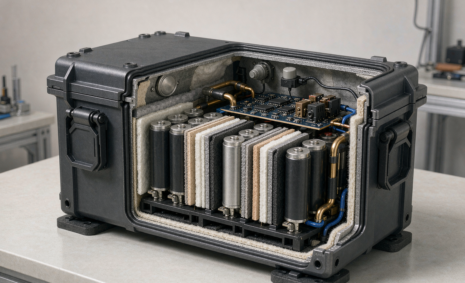
We design three barriers. The first is physical isolation: aerogel or mica sheets between cell groups, sized so a single cell’s energy cannot preheat its neighbor past onset within the five-minute window most equipment-duty scenarios allow. The second is directional venting: every enclosure has a calculated vent path that routes hot gas away from operators and away from the BMS board. The third is the enclosure itself — we keep at least 150 mm of clearance around the pack in the equipment and never let a plastic equipment shell double as the battery wall. For a custom battery solution fitted into someone else’s machine, I insist on a mechanical standoff drawing before we cut a single cell holder.
The BMS Safety Architecture for Field Equipment
The battery management system is where most preventable equipment incidents are stopped. Our equipment BMS uses a dual-sense architecture: two independent voltage and temperature sense paths, so a single broken sense line cannot hide an over-temperature condition. Over-current protection trips below 200 milliseconds, which matters because a stalled motor or a shorted connector can dump enough energy to weld contacts in under a second.
Three features I consider mandatory for equipment. A pyrotechnic fuse (pyro-fuse) that physically severs the high-current path on a hard fault, because a software contactor can weld shut. An isolation monitor that continuously checks the pack-to-chassis resistance and latches a fault if it drops below the IEC 62619 limit. And a contactor weld-detection routine that refuses to “close” if it sees voltage on the load side — a welded contact is how packs silently lose their last line of defense. I also add a temperature-compensated charge lockout: below 0°C the BMS will not accept a fast charge, because lithium plating at cold temperatures is a leading cause of field thermal events. This is the core of any battery solution safety equipment design we deliver.
Mechanical and Environmental Isolation
Equipment gets beaten. Our packs are built to MIL-STD-810H method 514.8 for vibration and 516.8 for shock, and we qualify the whole assembly, not just the cells. The single most important mechanical decision is the cell-to-busbar joint: we laser-weld pure nickel at Cpk ≥ 1.67, holding contact resistance under 0.15 mΩ at 25 N pull. A weak weld is a heater; I have torn down failed packs where a hand-soldered joint ran 40°C above its neighbors under load.
Environmental sealing follows the duty. For outdoor or wash-down equipment we specify IP65 to IP67 with an ePTFE pressure-equalization vent so the enclosure breathes without letting water in, plus a conformal coating (IPC-CC-830 Class 3) on the BMS. Cell preload is held at 0.3–0.7 MPa with a compression frame so cells cannot rattle and fret their welds over thousands of thermal cycles. None of this is visible to the buyer, but it is what keeps a lithium battery quiet and safe after three years in the field.
Commissioning and Operator-Safety Checklist
A pack is only as safe as its worst commissioning day. Before any equipment battery enters service we run a six-point field check: a 4-wire Kelvin DCIR baseline logged to the pack’s DataMatrix genealogy; a pre-charge verification so the inverter input capacitor does not see a hard inrush; an insulation-resistance megger reading above the IEC 62619 threshold; a vent-path clearance confirmation; a BMS fault-log download showing zero latched faults; and a state-of-health gate confirming cell capacity above 98 percent and voltage spread below 30 mV.
For transport and service, every pack we ship carries the IATA Section II marking and is shipped at or below 30 percent state of charge, which keeps it under the dangerous-goods fully-regulated threshold. Where the same energy cell feeds an aerial platform, we cross-map the build to the FAA and EASA carriage rules we use on our drone battery lines, because a safe battery solution should not change its safety language just because the equipment leaves the ground. The operator checklist is one page, laminated, and written for the technician who will never read the datasheet.
Frequently Asked Questions
What standards certify a battery solution for equipment safety?
The floor is UN38.3 T.1–T.8 for transport abuse and IEC 62133-2 for portable lithium cells, with IEC 62619 added for higher-energy or stationary-adjacent equipment. We layer IEC 62619, UL 2580 where the equipment is vehicle-like, and MIL-STD-810H for mechanical duty. No single mark covers field safety; the combination does.
How does LFP improve equipment battery safety versus NMC?
LFP’s thermal runaway onset is around 270°C versus roughly 210°C for NMC, a ~60°C margin that buys real time to trip the BMS and vent. LFP also avoids the cobalt-driven oxygen release that makes NMC propagation faster. For equipment near operators, that margin is why we default to LFP in most custom battery solution builds.
Can one battery solution serve both ground equipment and drones?
Partially. The cell safety language is shared — we cross-map ground packs to the FAA and EASA carriage rules we use on drone battery programs, and ship both at ≤30 percent state of charge under IATA Section II. But the mechanical and BMS envelope differs: airborne packs need tighter mass and higher C-rate headroom, so we design a common cell block and two pack architectures rather than forcing one.
How often should equipment batteries be re-qualified in the field?
We re-baseline DCIR and capacity at every scheduled service, typically every 12 months or every 400 full cycles, and we retire a pack if capacity falls below 80 percent, DCIR rises more than 30 percent, or cell spread exceeds 40 mV. The DataMatrix genealogy lets a technician see the pack’s whole safety history on a phone before it goes back into service.





