
Battery Solution Safety for Sensors
Sensors are everywhere now: industrial IoT nodes, environmental monitors, smart meters, agricultural soil probes, pipeline pressure transducers, and even the telemetry packs buried inside a drone battery system. But a sensor is only as trustworthy as the cell that powers it. Over my twelve years designing custom battery solution products for OEMs, I have watched far more sensor deployments fail from a weak or unsafe power source than from a faulty transducer. When a sensor sits unattended for three years on a remote oil pipeline, “safety” stops being a compliance checkbox and becomes the difference between a quiet asset and a field fire.
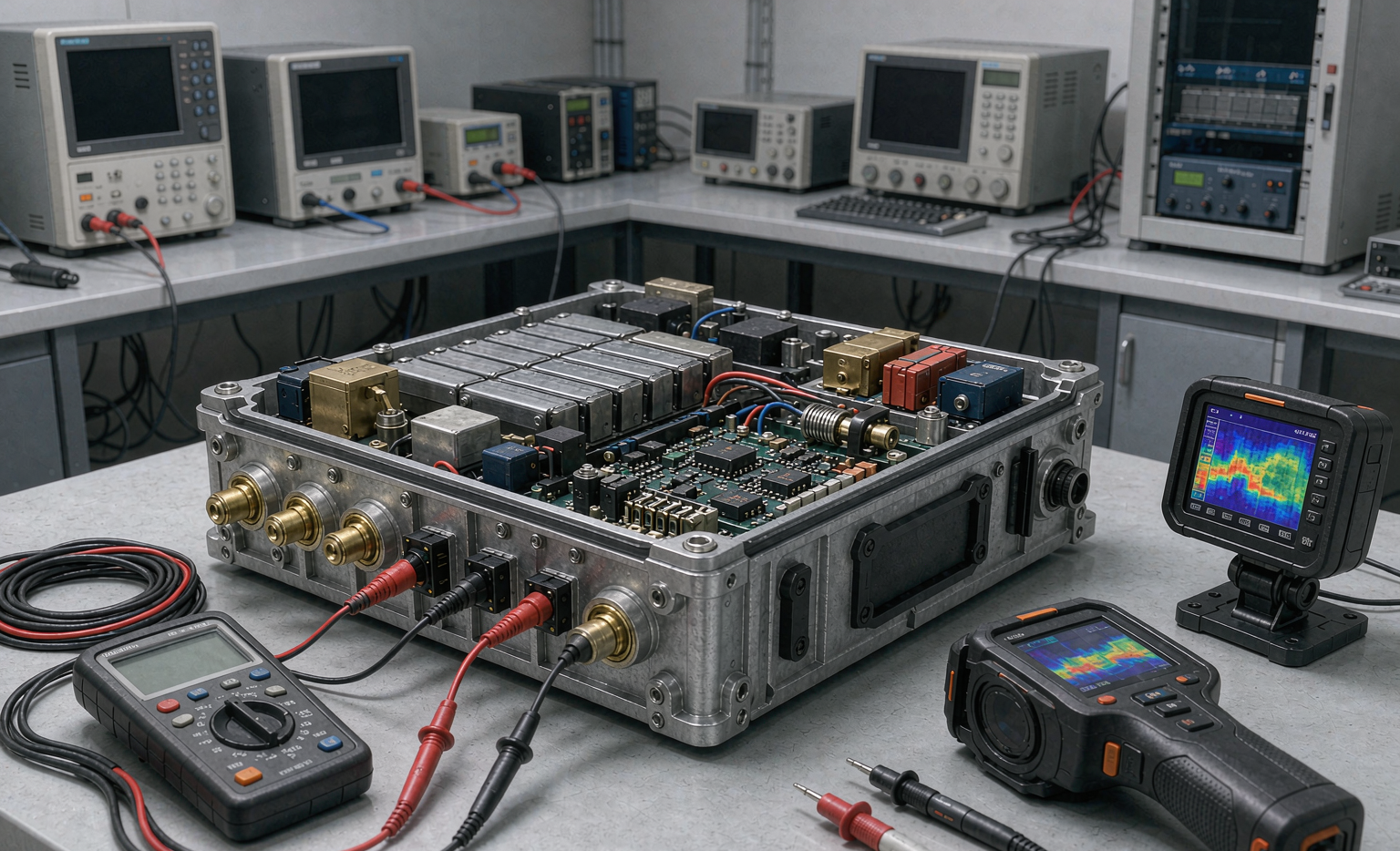
This guide is the field playbook I hand our engineering team when a customer asks for a battery solution rated for sensor duty. I will walk through the failure modes I actually see, the chemistry trade-offs, the certification boundaries written into UN38.3 and IEC 62133, and the validation protocol we run before a single pack ships.
Why Sensor Power Is a Safety Problem, Not Just an Uptime Problem
The first mistake teams make is treating a sensor battery like a phone battery. A phone is watched, charged, and replaced on a human timescale. A sensor is not. A wireless pressure node on a gas line may be sealed for 5–10 years with no human ever touching it. That changes the entire risk profile.
In my experience the three failure modes that turn a routine battery solution into a safety incident are: (1) slow over-discharge that drives a lithium cell below its floor and triggers copper dendrite growth; (2) thermal runaway triggered by a latent internal defect once the pack warms in a sealed enclosure; and (3) leakage from a venting event that corrodes the sensor electronics and the only signal path the operator has. None of these show up in a one-week bench test, which is exactly why a disciplined custom battery solution program matters.
- Latency of failure: a cell that fails in month 18 still represents a warranty and a site visit in year 2.
- Inaccessibility: the cost of a field swap is often 100× the cost of the pack, so safety margin is cheap insurance.
- Concentration risk: a fleet of 10,000 identical nodes means one design flaw scales to 10,000 incidents.
Cell Chemistry Choices for Sensor Duty Cycles
There is no single right cell. The right lithium battery chemistry depends on the discharge profile, the temperature envelope, and how long the node must survive. I routinely specify three families for sensor work.
Lithium-ion (NMC / LFP) for high-current sensor bursts
When a sensor must wake, transmit a LoRa or cellular burst at 500–2000 mA, then sleep for an hour, an 18650 or 21700 Li-ion cell is the natural fit. Nominal 3.6 V (NMC) or 3.2 V (LFP), a usable window of roughly 2.5–4.2 V, and a self-discharge around 2–3% per month. LFP wins on safety margin and cycle life; NMC wins on energy density. For a rugged outdoor node I lean LFP
Li-SOCl2 (lithium thionyl chloride) for ultra-low-current, long-life nodes
For a sensor that draws microamps and must run a decade, Li-SOCl2 delivers a staggeringly low self-discharge near 1% per year and a nominal 3.6 V. The trade-off is a glassy electrolyte and a hard venting behavior under abuse, which is why I only use it inside a protected custom battery solution with a certified pressure-relief path.
LiFePO4 for stationary, rechargeable sensor banks
Solar-powered environmental stations are the classic case. A small LFP bank charged by a 10 W panel gives you a rechargeable, thermally forgiving battery solution that shrugs off the 60 °C enclosure temperatures a sealed box sees in summer.
Thermal Runaway Boundaries: What UN38.3 and IEC 62133 Really Demand
When a customer says “make it safe,” I translate that into test evidence. Two standards sit at the core of every sensor battery solution we ship.
UN38.3 is the transport baseline, but its tests also reveal design fragility. The T.1–T.8 sequence—altitude simulation, thermal test (−40 °C to +75 °C), vibration, shock, external short circuit, impact, overcharge, and forced discharge—tells me whether a cell can survive the abuse a careless logistics chain or a hostile site will deliver. I have rejected otherwise excellent cells purely on a failed T.6 impact.
IEC 62133-2 (for portable lithium cells) and IEC 62619 (for industrial stationary cells) are where I prove internal-short and thermal-abuse resilience. In our lab I pair these with a 10 kΩ NTC thermistor on every parallel group and a BMS that opens the load at a conservative 60 °C — well below the onset of exothermic cascade in an NMC cell, which I budget at roughly 130 °C for the onset window.
- External short test limit: surface temperature must stay below 170 °C with no fire or explosion.
- Overcharge test (IEC 62133): charge to 2.0× the recommended limit, hold, and demonstrate no thermal event.
- We add a margin: our production cells are binned so the weakest parallel group still clears the limit by 15 °C.
Designing the BMS Safety Layer for Remote Sensors
For a sensor node the BMS is not about balancing a 100 A pack—it is about surviving neglect. The protections I consider non-negotiable in any custom battery solution for unattended sensors:
- Over-discharge lockout at 2.5 V/cell (LFP 2.0 V) with a permanent latch so a depleted pack cannot be silently re-enabled into a dangerous state.
- Over-current and short protection with a < 1 ms fuse-plus-FET combination, because a sensor cable chewed by a rodent is a real field event.
- Temperature windowing: disable charge below 0 °C and disable discharge above 60 °C.
- Single-fault tolerance: the protection must hold even if the primary FET welds shut, which is why I specify a redundant protection IC.
I also keep the BMS quiescent current below 5 µA so the protector itself does not drain a decade-life node. A lithium battery that dies because the safety chip ate the budget is not safe—it is just dead.
Hazardous and Outdoor Environments: Ingress, Venting, and Isolation
Sensors live where people will not. A methane monitor in a manhole, a salinity probe in seawater, a vibration sensor on a compressor—each demands a different enclosure story around the battery solution.
For intrinsically safe locations I design to IEC 60079 principles: the cell energy is kept below the ignition threshold of the local gas group, and any vent path is routed away from the sensor aperture. For outdoor nodes I specify IP67 minimum, with the cell isolated from the enclosure wall by an air gap so a single-point conductive fault cannot bridge to ground. When I reuse lessons from our drone battery programs, the big one is this: a pack that survives vibration on a airframe will survive a pothole on a utility truck, so the mechanical isolation work transfers directly.
Validation Protocol I Run Before Any Sensor Battery Ships
Before a custom battery solution reaches a customer, it passes what we call the “three-season” gate in our lab:
- Characterization: 50 cycles at −20 °C, +25 °C, and +60 °C to map real capacity versus the datasheet claim. I have caught cells losing 40% capacity at −20 °C that looked fine at room temperature.
- Abuse screening: a statistically sampled subset goes through nail penetration and overcharge while monitored by thermal cameras, confirming the vent path is predictable.
- Field emulation: the pack runs an accelerated duty cycle—one simulated year compressed into six weeks—to surface the slow failures a bench charge never reveals.
Only after all three clear do we release the battery solution for production. Certifications (UN38.3 transport, IEC 62133 cell, often IEC 62368-1 or UL 2054 for the assembly) are then documented per batch, not per design memory.
Conclusion
A safe battery solution for sensors is mostly invisible: it is the margin you built in, the test you refused to skip, and the BMS that locks out a bad state while nobody is watching. If you are specifying power for an unattended sensor, start from the failure modes and work backward to the chemistry and the certifications—not the other way around. That discipline is what turns a lithium battery into a dependable, safe field asset rather than a future incident report.
Frequently Asked Questions
How long should a sensor battery last in the field?
It depends on duty cycle, not just capacity. A microamp-draw Li-SOCl2 node can run 8–10 years; a bursty LoRa node on Li-ion typically runs 1–3 years. I size the battery solution from the worst-case transmit current, not the average, because the peak burst is what stresses the cell.
Can I use a standard drone battery pack for a fixed sensor node?
Rarely. A drone battery is optimized for high C-rate discharge and frequent cycling, with a BMS tuned for pilot oversight. A fixed sensor needs a protector tuned for neglect—ultra-low quiescent draw, decade-stable self-discharge, and a latching over-discharge cutoff. Reusing one for the other usually trades away the exact safety margin you need.
What certifications does a sensor battery solution need?
At minimum UN38.3 for transport, IEC 62133-2 for the portable cells, and for the assembly either IEC 62368-1 or UL 2054 depending on the market. Industrial stationary packs add IEC 62619. I document each batch because certification is evidence, not a one-time badge.
How do you prevent over-discharge in a rarely accessed sensor?
A latching BMS cutoff at 2.5 V/cell (2.0 V for LFP) that permanently opens the load until a qualified reset. In a custom battery solution for inaccessible nodes I also add a secondary protection IC so a welded primary FET cannot defeat the lockout. The pack dies quietly instead of limping into a dangerous deep-discharge state.





