Lithium Battery Testing for Solar Kits
When a customer asks me how we validate a lithium battery pack before it ships inside a solar kit, I give the same answer I give every procurement manager: a battery is only as trustworthy as the tests behind it. In my years as a senior lithium battery engineer at Horizon Power, I have seen too many off-grid solar installations fail not because the panels were sized wrong, but because the storage bank was never properly qualified. Lithium battery testing for solar kits is the discipline that separates a system running reliably for a decade from one that swells, trips the inverter, or loses half its capacity in its second season. It is also the part of the product that customers least often ask about, and the part that most determines whether they call us again in three years.
Why Solar Kits Demand a Different Test Philosophy
A solar kit is not a phone battery. It lives outdoors, swings between full sun and deep darkness, and is charged by a source whose output depends on clouds, sun angle, and season. That makes the duty cycle irregular and punishing. A lithium battery inside a solar kit sees partial-state-of-charge (partial-SoC) cycling, frequent shallow pulses, and long idle periods at elevated temperature. Generic consumer-cell test reports do not capture this reality, so we build a solar-specific validation plan from the cell up rather than borrowing a notebook from a power-tool program.
The first principle I teach my team is that you test the worst week, not the average week. If a kit sits at 60°C in a tin-roof shed during a heatwave, the cell must survive that, not just the lab-standard 25°C. We therefore map the real installation envelope — temperature range, daily throughput in amp-hours, and maximum C-rate — before a single cycle begins. A kit destined for a Nordic cabin is tested to −20°C; a kit for a Southeast Asian fish farm is tested at 55°C with 95% humidity. The envelope drives the test, not the other way around.
This philosophy also changes how we read a competitor’s spec sheet. A pack advertised as “2000 cycles” tested at a flat 25°C tells me almost nothing about a rooftop in July. The honest number only appears when the test profile matches the field profile, which is exactly what our solar validation procedure is built to do.
Cell-Level Screening: Capacity, Internal Resistance, and Voltage Matching
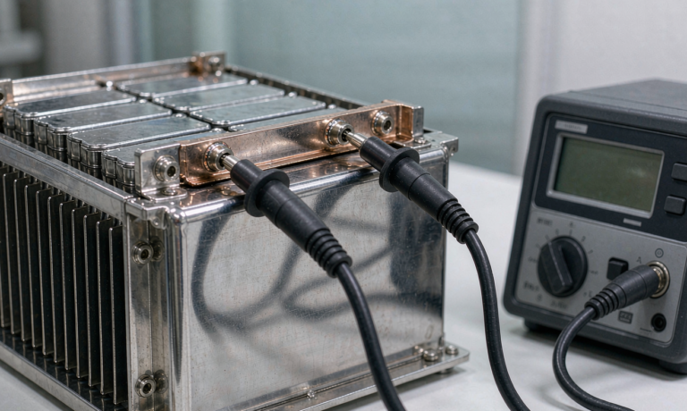
Every pack starts with incoming cell inspection. We measure actual capacity against the nameplate using a constant-current constant-voltage (CCCV) regimen at 0.2C, and we reject any cell more than 3% below spec. More important for pack longevity is internal resistance (IR). A 100 Ah LiFePO4 cell with IR above 0.6 mΩ will heat unevenly in a series string, so we bin cells to within 5% of IR and within 10 mV of open-circuit voltage before welding or busbar assembly.
Voltage consistency is the silent killer of solar banks. In a 4S or 8S configuration, a single weak cell forces the battery management system (BMS) to balance constantly, wasting harvested energy and generating heat. By screening at the cell level we keep pack imbalance under 20 mV at rest — a number I consider the floor for a professional solar lithium battery build. Skipping this step to save a few cents per cell is, in my experience, the most expensive shortcut in the industry.
We also log every cell’s serial number against its IR and capacity into our MES, so a field return three years later can be traced to a specific production lot. That traceability is part of what E-E-A-T-minded buyers should expect from a manufacturer, and it is something a trader reselling generic cells simply cannot offer.
UN38.3 and IEC 62133: The Non-Negotiable Safety Baselines
Before any pack leaves our facility it must clear UN38.3, the United Nations transport test simulating altitude, thermal, vibration, shock, external short circuit, impact, and overcharge. For air-freighted solar kits bound for overseas distributors, this is not optional — carriers operating under FAA and EASA rules will not accept a shipment without the UN38.3 test summary. We keep a current summary for every cell chemistry we ship, and we re-test whenever the cell supplier changes a formulation.
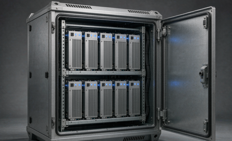
For the cells themselves we reference IEC 62133, the international safety standard covering short circuit, overcharge, forced discharge, and thermal abuse. When we design an industrial stationary pack we step up to IEC 62619 for the cells and UL 1973 for the battery system, plus IEC 62485-5 for stationary battery safety. A procurement spec that stops at “CE” without naming these standards is, in my experience, a red flag. CE is a declaration; the numbered IEC and UL standards are the actual evidence.
I want to be clear about why this matters for solar specifically: an overcharging LiFePO4 cell in a sealed outdoor enclosure has nowhere to vent. The safety margins proven by IEC 62133 and IEC 62619 are what keep a fault from becoming a fire. Testing is not bureaucracy; it is the difference between a warranty claim and an insurance claim.
Validating Cycle Life and Depth of Discharge in a Solar Profile
Cycle life on a datasheet — often “2,000 cycles at 80% DoD” — is measured under idealized lab conditions with a fresh cell at 25°C. Real solar use is different. We run accelerated life testing that mimics the actual solar duty: charge from a simulated MPPT source, hold at partial-SoC through the night, discharge on a variable load that follows a real household curve. The result is sobering — a pack rated for 2,000 full-equivalent cycles may deliver 3,500–5,000 cycles if the daily depth of discharge (DoD) is held near 50–60%.
This is the single biggest lever for total cost of ownership. A custom battery solution tuned to cap daily DoD at 50% can outlast a cheaper pack pushed to 80% DoD by a factor of two, even at higher upfront cost. I always show customers the levelized cost per kWh-cycle, not the sticker price, because that is the number that shows up on their P&L over a decade. We validate the claim by running representative packs to 80% capacity fade and publishing the curve, not just quoting the supplier’s brochure.
Charge Controller and BMS Co-Validation
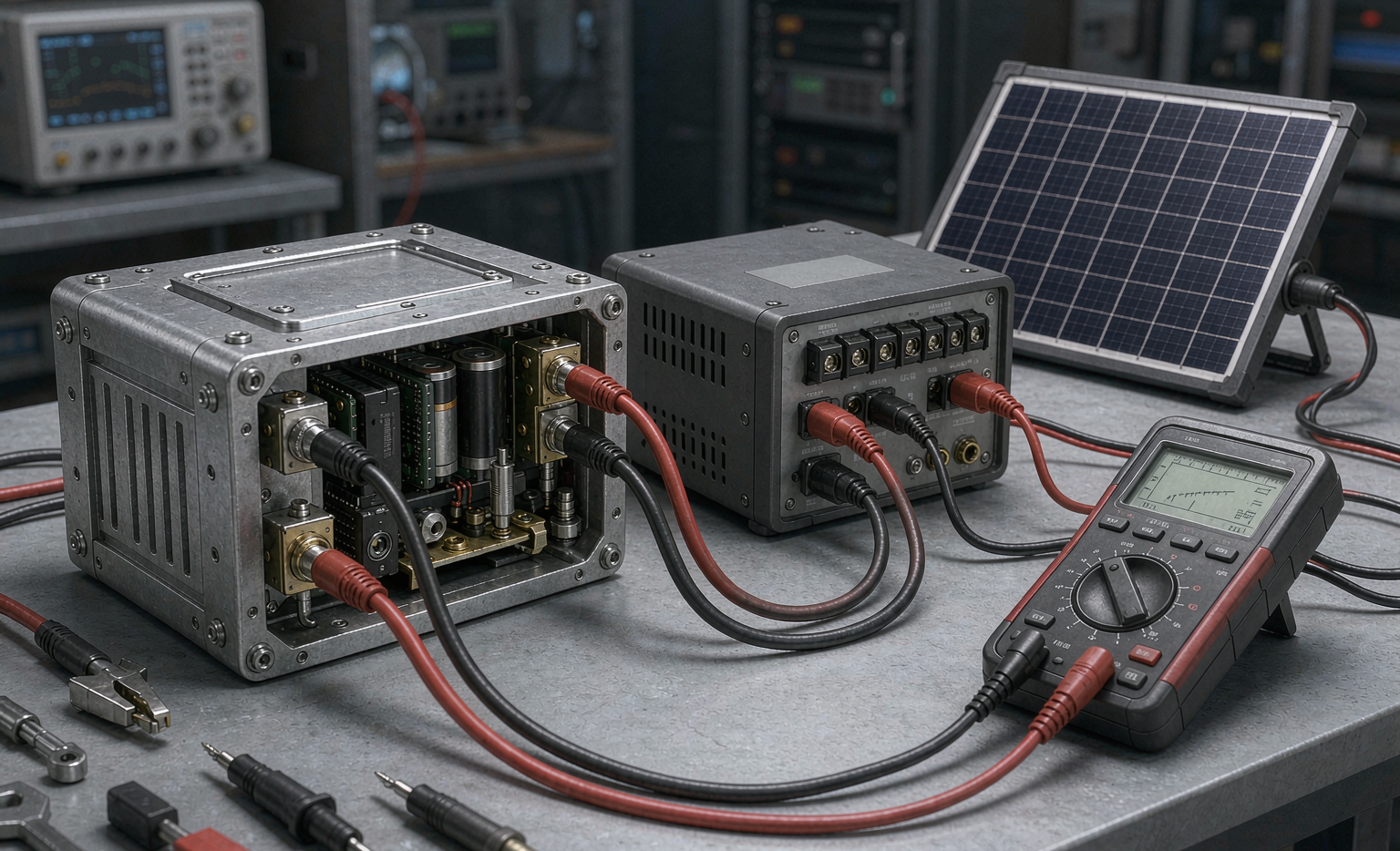
A solar kit is a system, and the battery cannot be tested in isolation. We validate the pack against the exact MPPT or PWM charge controller it will ship with, confirming the absorption voltage, float setpoint, and temperature-compensation curve all match the cell chemistry. A 12.8 V LiFePO4 bank wants a 14.4–14.6 V absorption; a 12 V NMC pack wants closer to 16.8 V. Mismatched setpoints are the most common cause of premature field failure I encounter, and they are entirely preventable with co-validation.
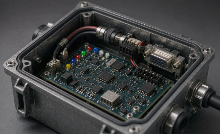
We also verify the BMS communication. For larger kits we use CAN or RS485 so the inverter and controller can read state-of-charge and fault codes. A BMS that silently disconnects under a legitimate surge is worse than no BMS, because the installer loses visibility. Co-validation means we trigger over-current, over-temperature, and cell-overvoltage events in the lab and confirm the controller responds gracefully — dropping to safe current rather than hard-faulting the whole array offline.
For integrators, I recommend demanding the BMS protocol document before purchase. A lithium battery that speaks only proprietary signaling locks you to one controller brand; one that exposes CAN or RS485 gives you freedom to evolve the kit later.
Environmental and Field Stress Testing
The final gate is environmental. We run thermal chambers from −10°C to +65°C, humidity dwell at 95% RH, and a salt-fog exposure for coastal kits. We also do a “real-sun” burn-in: a rack of prototype kits on the roof for 30 days, logging voltage, temperature, and yield every minute. Nothing beats live data. One coastal deployment taught us that our enclosure gasket, perfect in the chamber, let fine salt dust creep in through cable glands — a fix no lab test had surfaced, and one we would have missed without the roof trial.
For customers shipping to multiple climates, I recommend a regional test matrix. A lithium battery validated only in a temperate lab will surprise you in the desert or the tundra. Spend the extra weeks; the warranty claims you avoid pay for the testing ten times over. We document the matrix in the validation report so the customer’s own engineers can see precisely what their kit survived before it shipped.
Common Failure Modes Our Tests Are Designed to Catch
After a few thousand field returns, patterns emerge. The top three are: (1) cell mismatch from skipped screening, caught by our IR and voltage binning; (2) BMS-controller setpoint conflict, caught by co-validation; and (3) enclosure ingress in coastal or dusty sites, caught by salt-fog and the roof burn-in. Each of these is invisible on a generic datasheet and obvious only under a proper solar test plan. When a buyer asks what our testing actually buys them, I point to these three, because they are the reasons a Horizon Power bank is still cycling when a cheaper one has already been landfill.
Frequently Asked Questions
How many cycles should a solar lithium battery deliver?
For LiFePO4 chemistry, expect 2,000–4,000 full-equivalent cycles to 80% capacity, and 4,000–6,000 cycles if daily depth of discharge is held near 50–60%. NMC packs rate lower, typically 800–1,500 cycles, which is why we default to LiFePO4 for stationary solar storage where weight is not the primary constraint.
What test certificates matter most for solar kits?
At minimum, UN38.3 for transport and IEC 62133 for the cells. For stationary systems add IEC 62619 (cells), UL 1973 (battery), and IEC 62485-5 (safety). FAA/EASA compliance matters only for air shipment, but the UN38.3 test summary is required regardless of transport mode and should travel with every shipment.
Can I test a lithium battery with a normal multimeter?
A multimeter confirms pack voltage, but it cannot measure capacity, internal resistance, or state-of-health. Proper lithium battery testing for solar kits needs a capacity load tester, an IR meter, and a data logger tied to the charge controller. Field multimeter checks are useful for installation and troubleshooting, not for qualification or acceptance.
How do you size a custom battery solution for a specific solar kit?
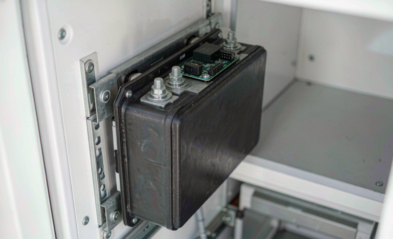
We start from daily kWh consumption and the longest no-sun stretch the site expects, then size for 2–3 days of autonomy at 50% DoD. We add the charge controller’s max current to set the C-rate, and we verify the enclosure against the site’s temperature and ingress rating. That spec becomes the test plan, so the pack is validated against the exact duty it will see in the field.